
End effector for surgical instrument, surgical instrument, and method for forming the end effector

a surgical instrument and end effector technology, applied in the field of end effectors for surgical instruments, can solve the problems of complicated construction of devices, high cost, and high cost of machining, and achieve the effect of improving grasping ability, manufacturing efficiently and inexpensively

Inactive Publication Date: 2006-08-17
ETHICON ENDO SURGERY INC
View PDF82 Cites 66 Cited by
  • Summary
  • Abstract
  • Description
  • Claims
  • Application Information

AI Technical Summary

Benefits of technology

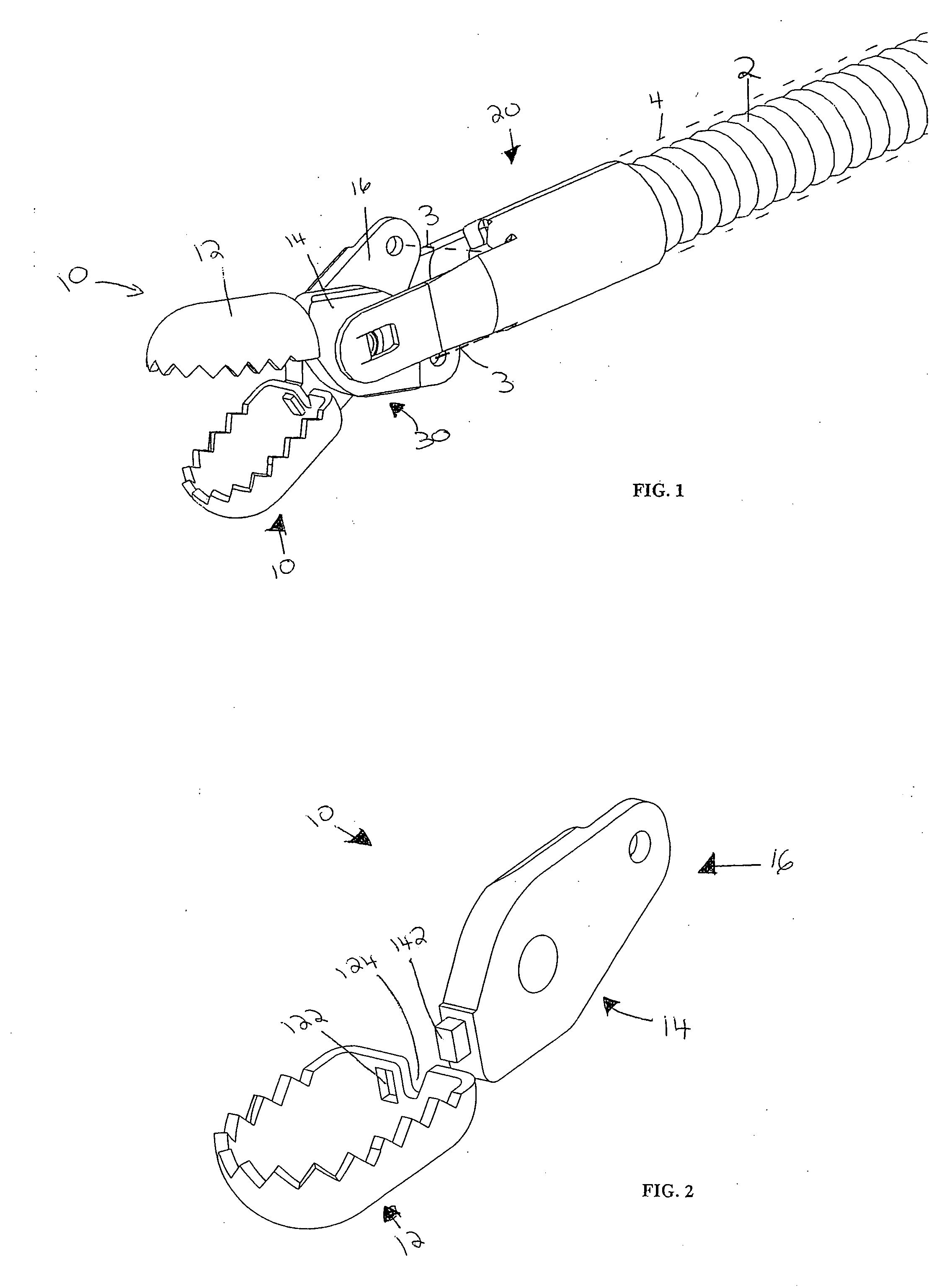
[0022] It is accordingly an object of the present invention to provide an end effector for a surgical instrument, a surgical instrument having the end effector, and a method for forming the end effector, that overcome the hereinafore-mentioned disadvantages of the heretofore-known devices and methods of this general type and that has teeth providing an improved grasping ability because of an inward curve that forms an undercut on their inner surface, that has a smooth outer surface, and that can be manufactured efficiently and inexpensively.
[0025] It is beneficial if the end effector is formed from two pieces that are connected together. Therefore, the tang and the end effector can be made by different processes to allow for flexibility in constructing each piece of the end effector and to take advantage of differing manufacturing processes.
[0026] Alternatively, the end effector can be made from a single sheet of thin material configured for inherent strength. Preferably, the material is a heat treatable stainless steel that can be easily formed in its annealed condition and heat treated after forming to improve its strength and hardness. In the one-piece embodiment of the jaw, the tang is formed from two separate tangs that both include axle and actuation holes.

Problems solved by technology

Ordinarily, these devices are of complicated construction, requiring the manufacturing and machining of precise miniaturized components, which are, therefore, generally quite expensive.
The Esser et al. jaws are made from stainless steel and, likewise, require expensive machining.
Sometimes, upon rapid withdrawal, the instrument accidentally exits the scope and whips into the air, flinging body fluids around the room and potentially in the endoscopist's or nurse's face.
The polymer outer sheath is delicate and can be damaged during printing.
Flexible endoscopes are expensive reusable devices, and the cost of repairing a worn out working channel is considerable.
Because biopsy forceps are passed so frequently through the working channel of a flexible endoscope, the channel is subject to wear.

Method used


Image

  • End effector for surgical instrument, surgical instrument, and method for forming the end effector
  • End effector for surgical instrument, surgical instrument, and method for forming the end effector
  • End effector for surgical instrument, surgical instrument, and method for forming the end effector

Examples


first embodiment

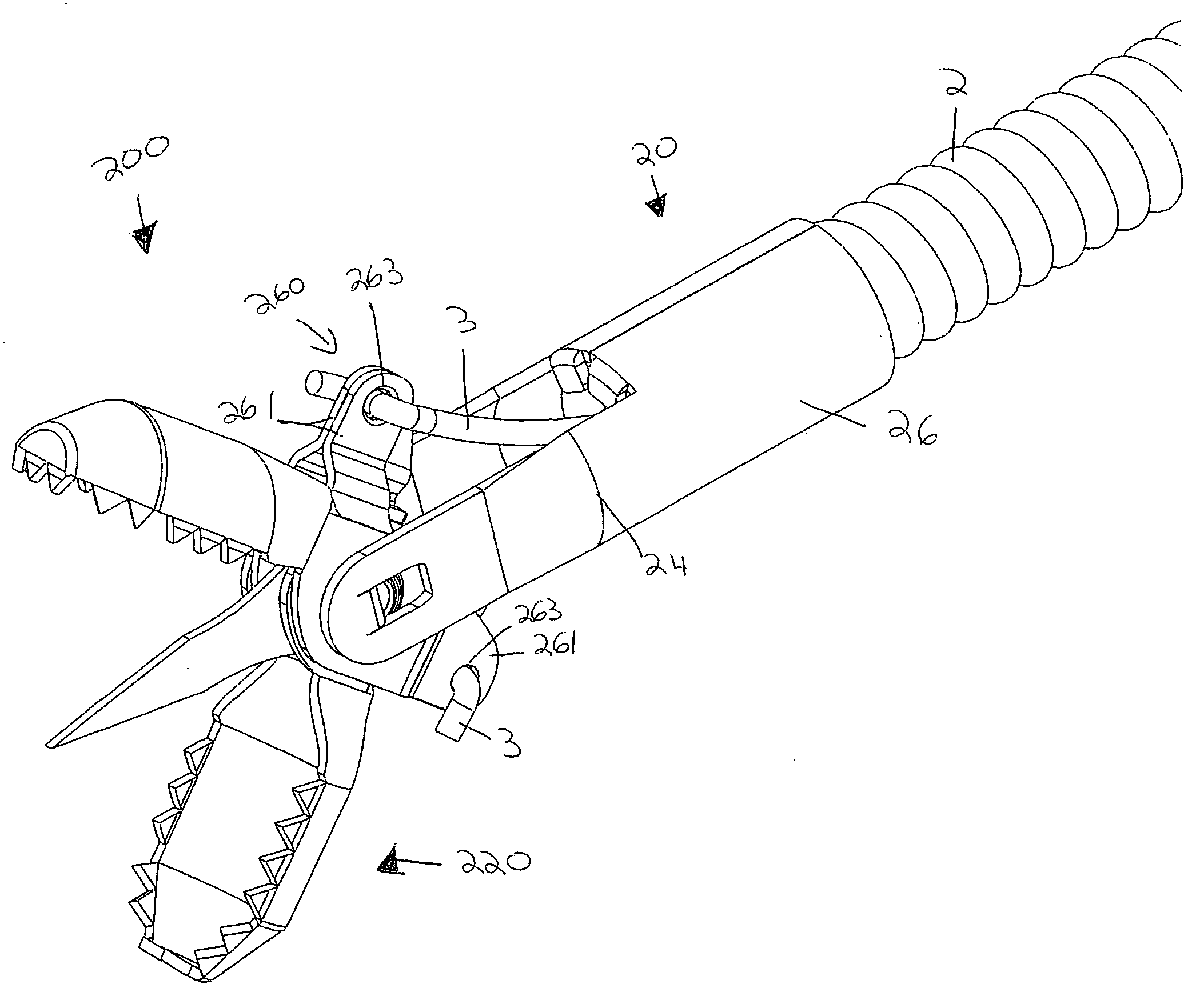
[0216] FIGS. 27 to 29, 68, and 69 show the actuating wires or rods 3. In that embodiment, the wires 3 extend longitudinally up to the control rod port 163, 263, bend ninety degrees to enter into the control rod port 163, 263, extend through both the control rod ports 163, 263 of each of the two parallel plates 161, 261 along an orthogonal portion 32, exit the control rod port 163, 263 of the second parallel plate 161, 261, and bend ninety degrees to, thereby, engage the tang 160, 260 without the possibility of falling out of the ports 163, 263. To actuate the forceps, a force is exerted on the rod 3. The S-bend of the wire 3 significantly reduces any possibility that the wire 3 becomes dislodged from the tang 160, 260.

[0217] FIGS. 74 to 79 illustrate another embodiment 360 of the tangs 160, 260 and second and third embodiments of the wires 3 shown in the previous figures.

[0218] As set forth above, the wire 3 is attached to the jaw 10 to allow the wire 3 to freely rotate and to allo...

third embodiment

[0222] To attach the wire 3 to the jaw 10, the wire 3 extends longitudinally from the proximal end of the forceps device up to the control rod port 363 along a first portion 31, bends ninety degrees to enter into the control rod port 363, extends through both the control rod ports 363 of each of the two parallel plates 361 along an orthogonal portion 32, exits the control rod port 363 of the second parallel plate 361, and ends. This third embodiment of the wire 3 similarly reduces any possibility that the wire 3 becomes dislodged from the tang 360.

[0223] To effect the reduction of unintended wire 3 removal, one plate 361 of the two parallel plates 161, 261 has a hooded wire support 365. The hooded wire support 365 is configured provide support to the wire 3 and, thereby prevent removal of the wire 3 from the tang 360. The hooded wire support 365 is substantially U-shaped in cross-section and, therefore, has a vertical first leg 366, a horizontal portion 367, and a vertical second le...


PUM


Abstract

An end effector for an endoscopic surgical instrument having a longitudinal body with proximal and distal ends and an actuator at the proximal end of the body includes a clevis to be connected to the distal end of the body and two jaws. Each of the jaws has a tang portion pivotally connected to the clevis and to be connected to the actuator for pivoting the jaw. The jaw has body portion with a lateral side having substantially straight opposing edges and a proximal portion connecting the lateral side to the tang portion and a nose portion connected to the lateral side and having substantially linear edges at an angle to the edges of the lateral side. The hollow body and nose portions define a biopsy cup for receiving a tissue sample therein and the opposing and linear edges form a pinching surface for contacting extremities of the tissue sample.

Description

CROSS-REFERENCE TO RELATED APPLICATION [0001] This application claims the priority, under 35 U.S.C. § 119, of U.S. Provisional Patent Application No. 60 / 648,538 filed Jan. 31, 2005, and U.S. Provisional Patent Application No. 60 / 738,279 filed Nov. 18, 2005, the entire disclosures of which are hereby incorporated herein by reference in their entireties.BACKGROUND OF THE INVENTION [0002] 1. Field of the Invention [0003] The present invention relates to an end effector for a surgical instrument, a surgical instrument having the end effector, and a method for forming the end effector. [0004] The end effector of the present invention is for a surgical instrument and is made from two pieces. The pieces are joined to form the end effector. The pieces can be made by powder metal processes, machining, stamping, fine blanking, deep drawing, casting etc. The pieces can be joined by riveting, welding, soldering, brazing, folded tabs, pressing, etc. The pieces can be made from the same materials...

Claims


Application Information

Patent Timeline
Patent Type & Authority Applications(United States)
IPC IPC(8): A61B17/28
CPCA61B10/04A61B10/06A61B17/29A61B2017/2902A61B2017/2905A61B2017/2919A61B2017/2926A61B2017/2932A61B2017/320064
Inventor BALES, THOMAS O.PALMER, MATTHEW A.SMITH, KEVIN W.KLINE, KOREY ROBERTDEVILLE, DEREK DEE
Owner ETHICON ENDO SURGERY INC
Learn More