
Ultrasonic imaging apparatus and ultrasonic image processing apparatus, method and program

Inactive Publication Date: 2006-08-17
FUJIFILM HLDG CORP +1
View PDF14 Cites 29 Cited by
  • Summary
  • Abstract
  • Description
  • Claims
  • Application Information

AI Technical Summary

Benefits of technology

[0021] According to the first aspect of the present invention, since a speckle analysis result image is generated by analyzing a spackle image and displayed as a moving image, medical diagnoses by doctors are facilitated and the diagnostic efficiency can be raised, and thereby, the quality of medical diagnoses can be improved. Further, according to the second aspect of the present invention, since a band limited image in which spatial frequencies are limited to a higher band than those of normal ultrasonic images is generated, spackle patterns generally having high spatial frequencies can be displayed in an easily viewable condition. Therefore, in the case where tissue properties of a part to be observed are determined based on speckle patterns, the ultrasonic imaging apparatus etc. having such a function can be utilized for effective diagnostic support.

Problems solved by technology

However, in the present circumstances, no ultrasonic imaging apparatus having such a function has been proposed.

Method used


Image

  • Ultrasonic imaging apparatus and ultrasonic image processing apparatus, method and program
  • Ultrasonic imaging apparatus and ultrasonic image processing apparatus, method and program
  • Ultrasonic imaging apparatus and ultrasonic image processing apparatus, method and program

Examples


first embodiment

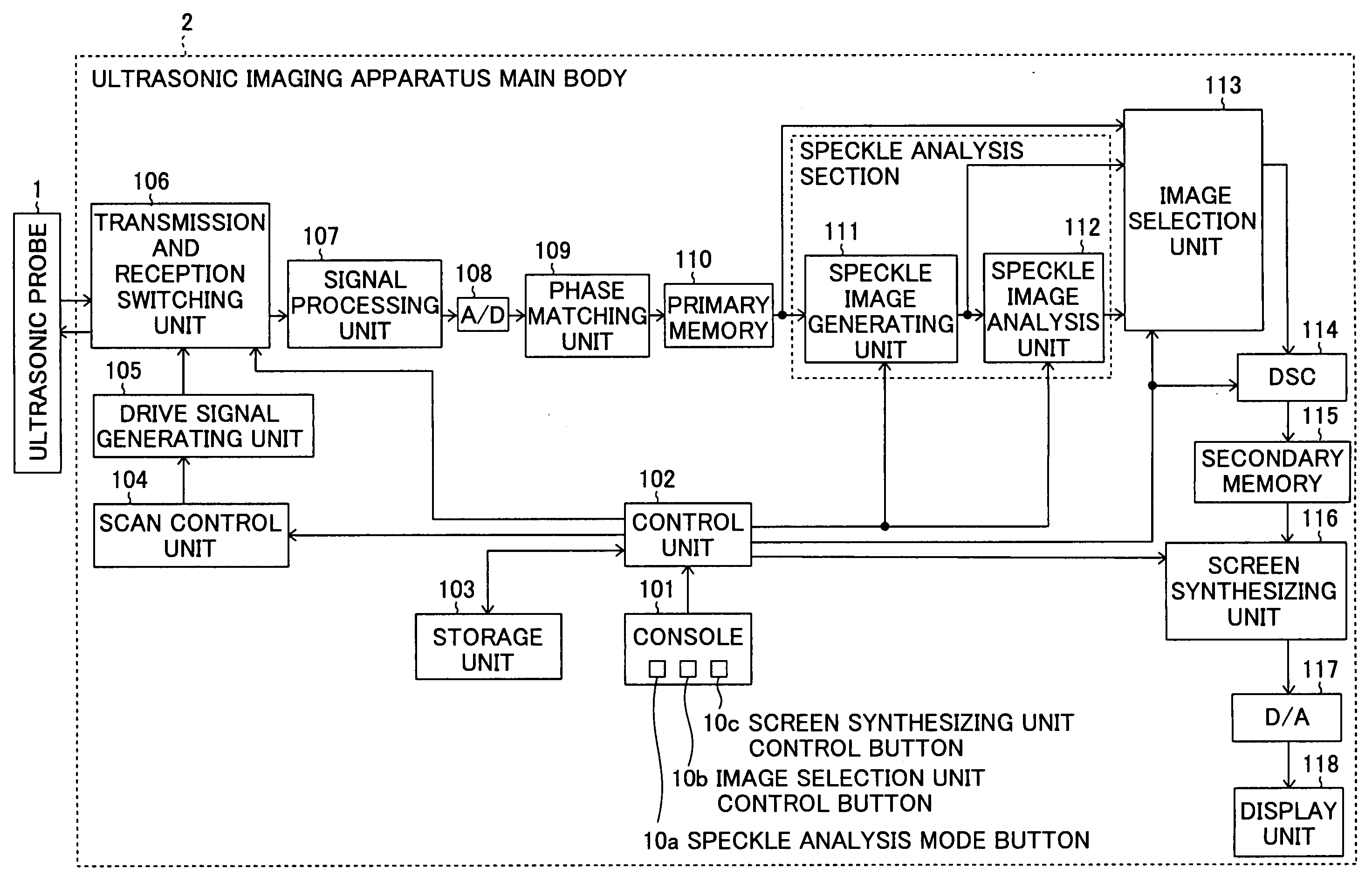
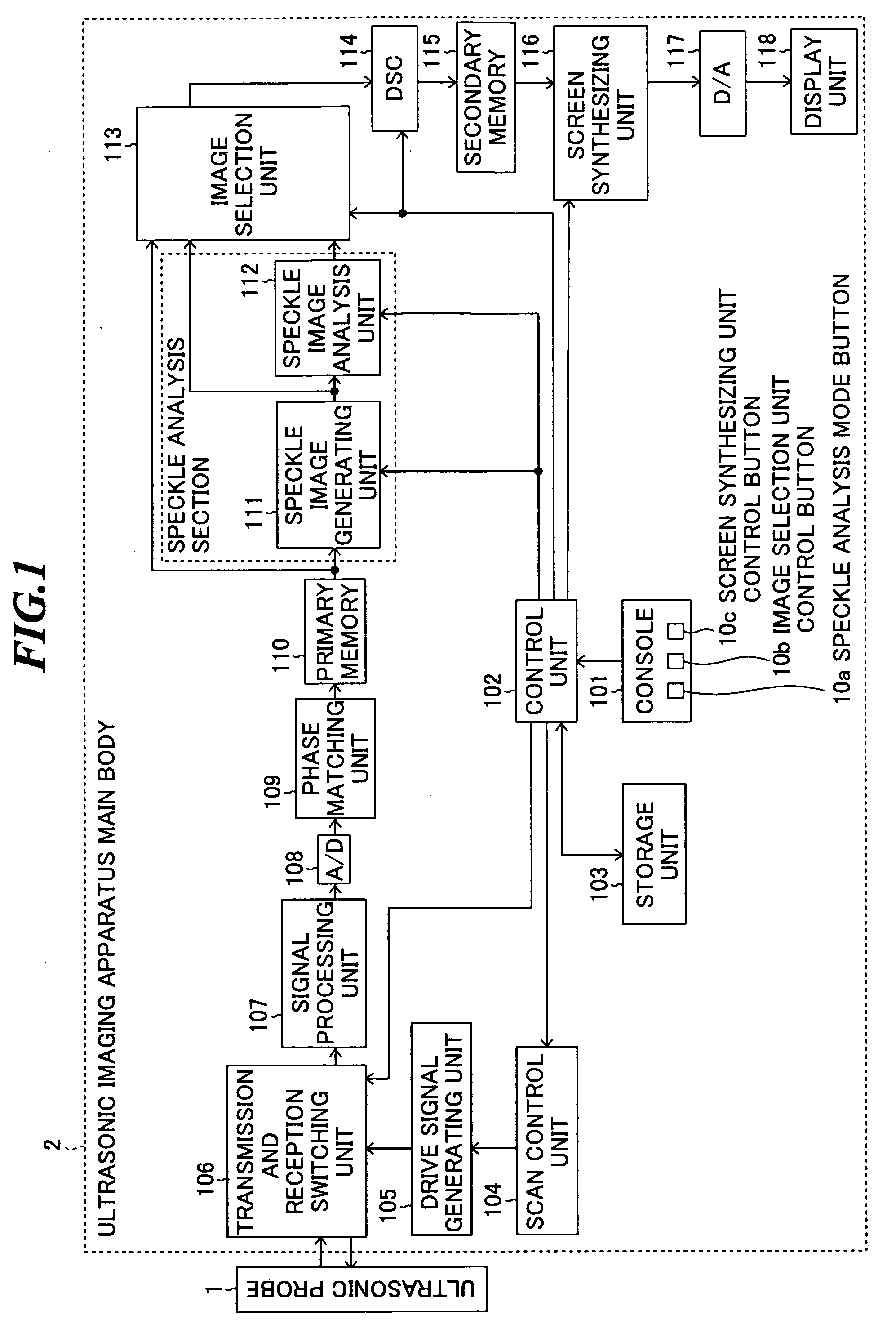
[0061]FIG. 1 is a block diagram showing a constitution of an ultrasonic imaging apparatus according to the present invention. This ultrasonic imaging apparatus includes an ultrasonic probe 1 for transmitting ultrasonic waves and receiving ultrasonic echoes, and an ultrasonic imaging apparatus main body 2 for controlling the transmission and reception of ultrasonic waves and generating an ultrasonic image based on reception signals obtained by detecting the ultrasonic echoes.

[0062] The ultrasonic probe 1 includes an ultrasonic transducer array in which plural ultrasonic transducers are arranged. Each ultrasonic transducer is fabricated by forming electrodes on both ends of a material having a piezoelectric property (piezoelectric material) such as a piezoelectric ceramic represented by PZT (Pb (lead) zirconate titanate) or a polymeric piezoelectric element represented by PVDF (polyvinylidene difluoride). When a voltage is applied to the electrodes of such an ultrasonic transducer by ...

second embodiment

[0101] Next, an ultrasonic imaging apparatus according to the present invention will be described.

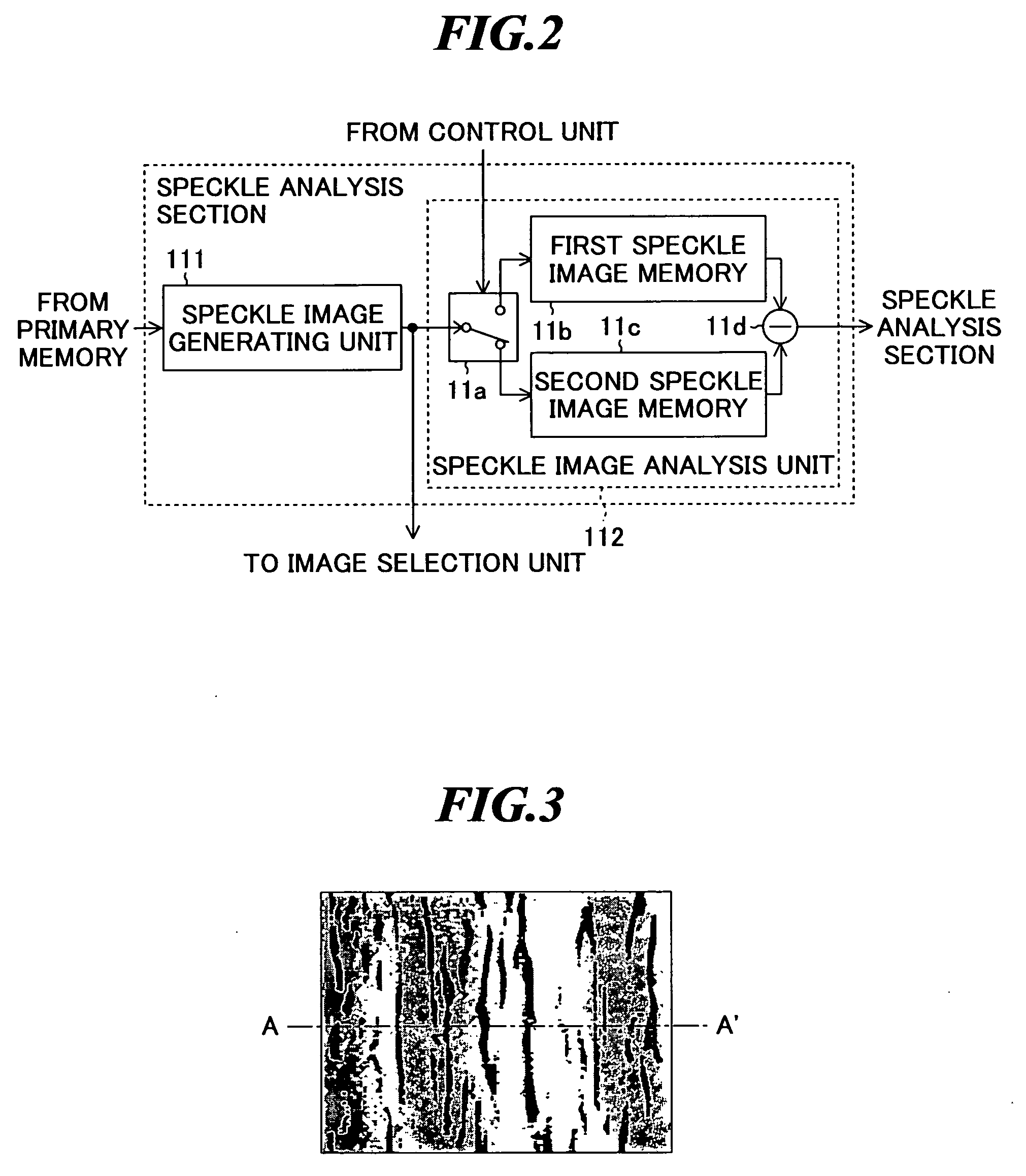
[0102]FIG. 8 is a block diagram showing part of the ultrasonic imaging apparatus according to the embodiment. As shown in FIG. 8, the ultrasonic imaging apparatus according to the embodiment includes a speckle image generating unit 121 and a speckle image analysis unit 122 as a speckle analysis section. Other constitution and operation are the same as those in the ultrasonic imaging apparatus shown in FIG. 1.

[0103] The speckle image generating unit 121 includes a LPF (low-pass filter) 12a for extracting low frequency components of an image signal represented by the original data outputted from the first memory 110, a first speckle image generating part 12c for generating first speckle image data based on the low frequency components extracted by the LPF 12a, a HPF (high-pass filter) 12b for extracting high frequency components of an image signal represented by the original data outputt...

third embodiment

[0111] Next, an ultrasonic imaging apparatus according to the present invention will be described.

[0112]FIG. 11 is a block diagram showing a part of the ultrasonic imaging apparatus according to the embodiment. As shown in FIG. 11, the ultrasonic imaging apparatus according to the embodiment includes a speckle image generating unit 121 and a speckle image analysis unit 130 as a speckle analysis section. The constitution and operation of the speckle image generating unit 121 are the same as those described in the second embodiment. Other constitution and operation are the same as those in the ultrasonic imaging apparatus shown in FIG. 1.

[0113] The speckle image analysis unit 130 generates speckle image analysis data representing depth-dependent change of a difference between low frequency component intensity and high frequency component intensity contained in a speckle image for one frame. The speckle image analysis unit 130 includes a first frequency processing part 13a, a second f...


PUM


Abstract

An ultrasonic image processing apparatus capable of analyzing speckle information contained in the entire ultrasonic image and displaying the analysis results as a moving image. The ultrasonic image processing apparatus is an apparatus for processing reception signals, which are obtained by transmitting ultrasonic waves toward an object to be inspected and receiving ultrasonic echoes from the object, to generate ultrasonic image data, and the apparatus includes: a speckle image generating unit for generating speckle image data representing a speckle image based on original data generated by performing signal processing on the reception signals and representing ultrasonic image information on the object; and a speckle image analysis unit for performing analysis of the speckle images represented by the speckle image data generated by the speckle image generating unit to generate speckle analysis result image data representing analysis results as a moving image.

Description

BACKGROUND OF THE INVENTION [0001] 1. Field of the Invention [0002] The present invention relates to an ultrasonic imaging apparatus for generating ultrasonic images based on reception signals obtained by transmitting ultrasonic waves and receiving ultrasonic echoes, and an ultrasonic image processing apparatus for processing image data in such an ultrasonic imaging apparatus. Further, the present invention relates to an ultrasonic image processing method and an ultrasonic image processing program to be used in such an ultrasonic image processing apparatus. [0003] 2. Description of a Related Art [0004] In medical fields, various imaging technologies have been developed in order to observe the interior of an object to be inspected and make diagnoses. Especially, ultrasonic imaging for obtaining interior information of the object by transmitting and receiving ultrasonic waves enables image observation in real time and provides no exposure to radiation unlike other medical image techno...

Claims


Application Information

Patent Timeline
IPC IPC(8): A61B8/00
CPCA61B8/14G01S7/52025G01S7/52044G01S7/52047G01S7/52074
Inventor SATOH, YOSHIAKI
Owner FUJIFILM HLDG CORP
Learn More