
Air handling unit mixing method and system

Inactive Publication Date: 2006-08-17
YORK INT
View PDF7 Cites 28 Cited by
  • Summary
  • Abstract
  • Description
  • Claims
  • Application Information

AI Technical Summary

Benefits of technology

[0010] An advantage of the present invention is that the incoming air is mixed in the mixing chamber to produce air having a substantially uniform temperature and composition to pass over the heating or cooling coil.
[0011] Another advantage of the present invention is that mixing of the air occurs without the requirement of having an air blender, which increases the pressure drop and fan requirements for the air handling system.
[0012] Another advantage of the present invention is the mixing of the air streams with minimal pressure drop. The substantial lack of pressure drop reduces the fan operating costs by requiring either a smaller fan and / or less horsepower to circulate air.

Problems solved by technology

Ineffective mixing of air streams may result in non-uniform heating or cooling of the conditioned space, and in some cases may cause damage to the system.
Directing the streams toward each other has the drawback that much of the air in one stream passes through the second stream without adequate mixing.
The use of an air blender results in more equipment and a larger pressure drop for the system.
The larger pressure drop may require a larger fan and may require more fan energy, even when the system is operating with only one of the outdoor air or return air dampers being open.
This is a particular problem when the outdoor temperature is excessively cold, is excessively warm, or when the outdoor air contains pollutants.
If the outdoor air is sufficiently cold and mixing of the return air is insufficient, the cold air stratifies (i.e., separates) in the air handling system and freezes water in the heating or cooling coil.
Current systems fail to provide sufficient control of the ratio of outside air to inside air and fail to provide sufficient mixing of the air passing over the heating or cooling coil to prevent freezing of the water in the coil and to minimize the concentration of pollutants present in the indoor space.

Method used


Image

  • Air handling unit mixing method and system
  • Air handling unit mixing method and system
  • Air handling unit mixing method and system

Examples


Embodiment Construction

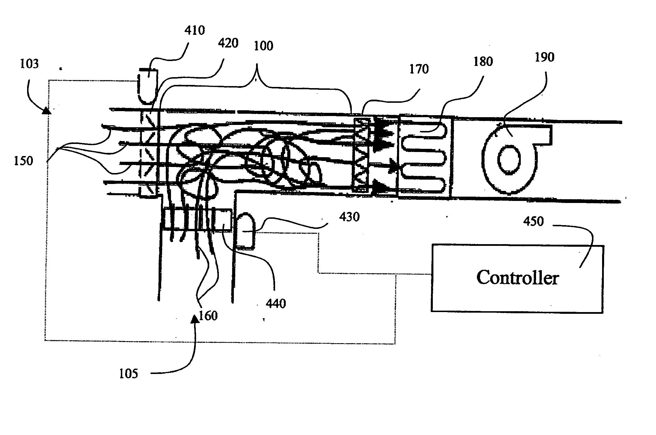
[0023]FIG. 1 schematically illustrates a known HVAC system air handling unit. The air handling unit includes a mixing space 100, which receives air from a first inlet 103 and a second inlet 105. First inlet 103 includes a first linked actuator 110, and a first parallel blade damper 120. Second inlet 105 includes a second linked actuator 130, and a second parallel blade damper 140. The first inlet air stream 150, which is preferably air brought from the outdoors, passes through first parallel blade damper 120 into the mixing space 100. The second inlet air stream 160, which is preferably return air brought from the indoor space, passes through second parallel blade damper 140 into mixing space 100. The first and second linked actuators 110 and 130 move the first and second parallel blade dampers 120 and 140 together from a single control signal. The linkage of the first and second linked actuators 110 and 130 may be a mechanical linkage or a single control signal provided to both fir...


PUM


Abstract

A mixing chamber for an air handling unit having a first inlet, second inlet and an outlet. The first inlet receives a first air stream. The second inlet to receives a second air stream. The outlet discharges a mixed airflow. The first inlet includes a first damper having an opposed blade configuration for controlling the flow of the first air stream and the second inlet includes a second damper having an opposed blade configuration for controlling the flow of the second air stream. The mixing chamber also includes a control arrangement to control operation of the first and second damper. The control arrangement is configured to independently open and close each of the first and second dampers to regulate airflow into the mixing chamber.

Description

FIELD OF THE INVENTION [0001] The present invention is directed to an air handling unit for a heating, ventilation and air-conditioning (HVAC) system. In particular, the present invention is directed to a system and method for mixing air in variable air volume air handling systems. BACKGROUND OF THE INVENTION [0002] HVAC systems typically include an air handling unit. The air handling unit contains various components for conveying air from and into an indoor space. Among the components of the air handling unit is a mixing box. A mixing box is a component that mixes two or more streams of air in order to provide a mixed stream of air having a substantially uniform temperature and composition. Ineffective mixing of air streams may result in non-uniform heating or cooling of the conditioned space, and in some cases may cause damage to the system. [0003] One type of air handling unit used commercially is a variable air volume system. A variable air volume system is a system that provide...

Claims


Application Information

Patent Timeline
IPC IPC(8): F24F13/04F24F11/00
CPCF24F11/0009F24F11/0012F24F13/04Y02B30/78F24F2011/0026F24F2011/0027F24F13/1413F24F11/30F24F2110/10F24F2110/70F24F2110/72Y02B30/70F24F11/74F24F11/63
Inventor KETTLER, JOHN PERLOT
Owner YORK INT
Learn More