Magnetic flow meter with unibody construction and conductive polymer electrodes

a technology of magnetic flow meter and conductive polymer electrode, which is applied in the direction of electromagnetic flowmeter, volume/mass flow, measurement devices, etc., can solve the problems of not being conducive to bulky devices, magflow meters are typically large, and have not been used or applied in the semiconductor industry. , to achieve the effect of reducing the cost and complexity of lining the conduit, reducing the cost and assembly complexity, and reducing the noise of background electrical nois

Active Publication Date: 2006-08-10
ENTEGRIS INC
View PDF19 Cites 21 Cited by
  • Summary
  • Abstract
  • Description
  • Claims
  • Application Information

AI Technical Summary

Benefits of technology

[0009] An advantage of the various embodiments of the invention is that the conduit is fabricated from a dielectric material, without incorporating a metallic outer housing, thus reducing the cost and complexity of lining the conduit. Furthermore, the conduit is fabricated to easily and directly accept the electrode and electromagnetic assemblies, further reducing cost and assembly complexity.
[0010] Another advantage of the various embodiments of the invention is that the conductive polymer (or plastic) electrodes are resistant to chemical attack. As disclosed in U.S. Pat. No. 5,449,017, the conductive polymer (or plastic) electrodes may be constructed from a polymer material suitable for the particular medium under measurement, including but not limited to blends of PTFE or PFA. These electrodes also feature shields that are molded into the electrode assembly to reduce background electrical noise.
[0012] Another advantage of one of the various embodiments of the invention utilizes an electrode construction that electrically drives an electrode shield circuit (electrodes and cabling), thereby reducing the effective cable impedance relative to the complex impedance of the fluid / electrode interface to provide a more accurate measurement of the electromotive force.

Problems solved by technology

Despite the technological advantages of magnetic flow meters, they have not typically been used or applied in the semiconductor industry.
This is thought to be due to the ultra pure and highly corrosive nature of the liquids (acids and bases such as HCl and NH4OH) and gases commonly used in the industry.
In addition, magflow meters are typically large, bulky devices not conducive to the small size and flow rate requirements of the semiconductor industry.

Method used


Image

  • Magnetic flow meter with unibody construction and conductive polymer electrodes
  • Magnetic flow meter with unibody construction and conductive polymer electrodes
  • Magnetic flow meter with unibody construction and conductive polymer electrodes

Examples


Embodiment Construction

[0027] The invention is generally directed to an apparatus and a system for measuring the flow velocity of corrosive chemical fluids in a semiconductor fabrication facility. While the invention is not necessarily limited to such an application, the invention will be better appreciated using a discussion of example embodiments in such a specific context.

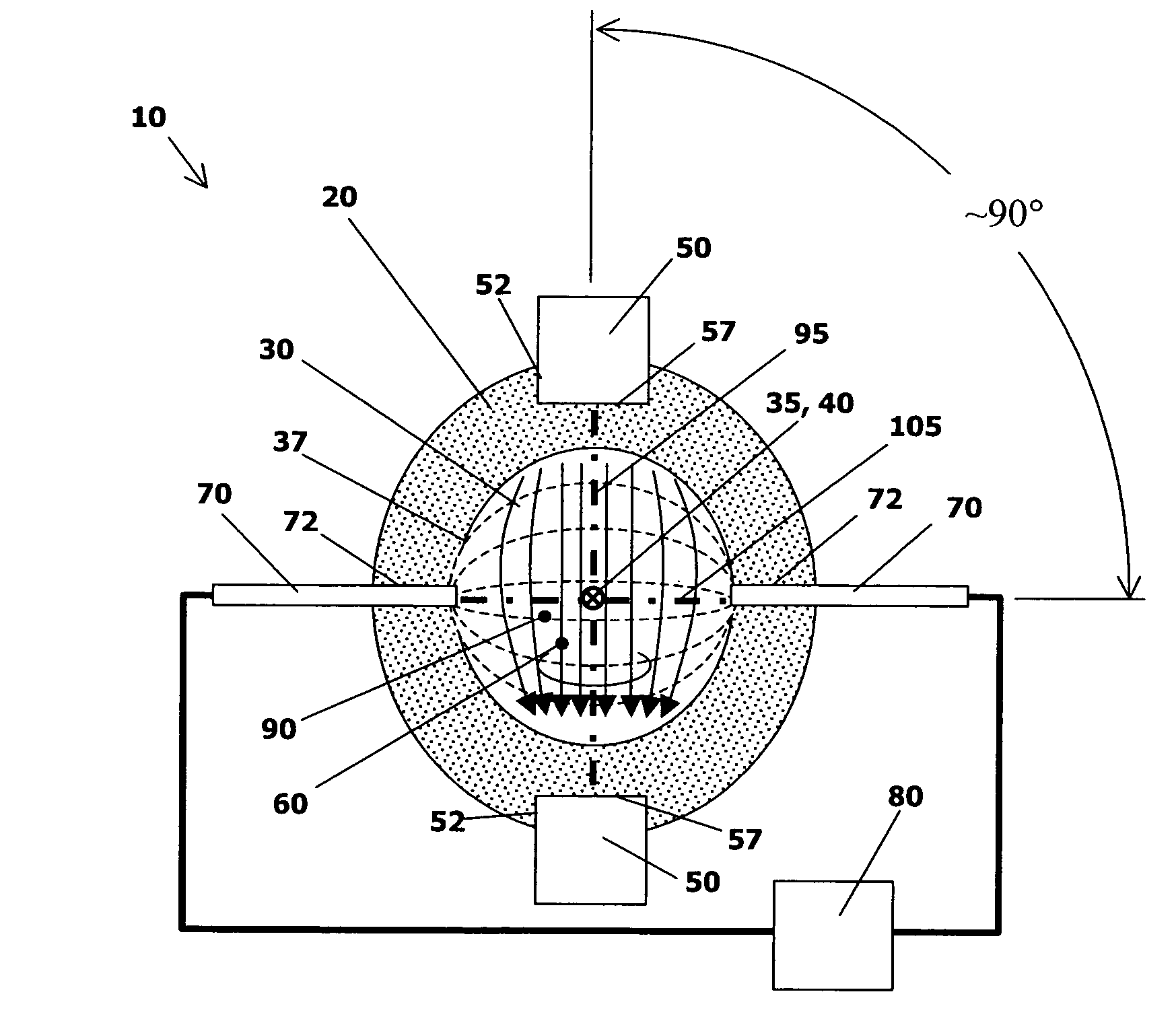
[0028] Magnetic flowmeters are used to measure the volumetric flow rate of electrically conductive liquids. They operate on Faraday's principle of induced voltage, expressed by

emf∝B·L·U

where emf is a electromotive force (volts), B is a magnetic flux density (gauss), L is a spanwise length or thickness through the conductive liquid across which emf is generated (e.g., cm), and U is the local velocity of the conductive liquid being metered (e.g., cm / sec).

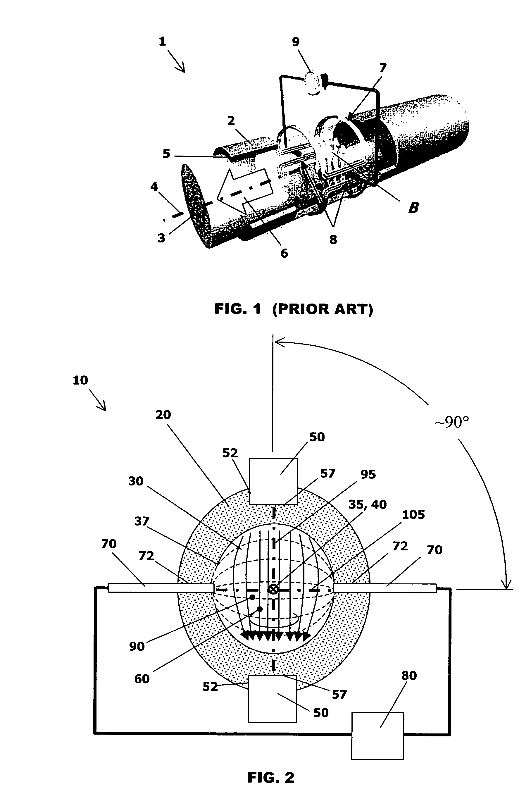
[0029] Referring to FIG. 1, there is illustrated a prior art magnetic flow meter 1 that includes a housing 2 defining a conduit 3 having a central flow axis 4, a wetted perimeter 5...


PUM


Abstract

A magnetic flow metering device and method is disclosed for the measurement of corrosive flow streams. The device utilizes a unibody construction wherein the flow conduit is constructed entirely from an insulative, non-conducting material without resorting to a metallic outer housing. The portions of the electrodes in contact with the flow stream are made of a suitable conductive polymer material, resistant to the corrosive media. The electrodes also feature shields that are molded into the electrode assembly to reduce background electrical noise. The invention also utilizes an electrical configuration that actively drives the electrode shield circuit (electrodes as well as cabling) to provide a more accurate measurement of the electromotive force.

Description

FIELD OF THE INVENTION [0001] The invention relates to the monitoring and measurement of fluid flow in a conduit and particularly to magnetic flow meters for use in the semiconductor industry. BACKGROUND OF THE INVENTION [0002] The theory of operation of a magnetic flow meter (‘magflow meter’) is based on Faraday's law of induced voltage, wherein an electromotive force (EMF) is produced that is proportional to the velocity of a conducting medium that flows through a magnetic field. Typically, in the case of a magflow meter, the flowing medium is a conductive medium passed through a section of conduit that is subjected to a transverse magnetic flux. As the conductive fluid passes through the conduit, the resulting EMF is detected by electrodes that are mounted to the conduit walls and in physical contact with the medium. To prevent shorting of the EMF, the conduit walls are constructed of a non-conductive material. [0003] Magflow meters have found application in the process control i...

Claims


Application Information

Patent Timeline
IPC IPC(8): G01F1/58
CPCG01F1/588G01F1/60G01F1/58G01F1/56
Inventor WEHRS, DAVID L.CHINNOCK, ROBERT T.
Owner ENTEGRIS INC
Why Eureka
Try Eureka