Current mode waveform generator followed by a voltage mode buffer

Inactive Publication Date: 2006-08-03
ANALOG DEVICES INC
View PDF16 Cites 5 Cited by
  • Summary
  • Abstract
  • Description
  • Claims
  • Application Information

AI Technical Summary

Benefits of technology

[0004] In a first embodiment of the invention, there is provided a power saving circuit that creates a fast changing high resolution signal for testing of a pin of a device under test. The circuit of the invention includes a current mode waveform generator followed by a voltage mode buffer. For example, the current mode waveform generator may be an A-linear or KT-linear stage. A current mode waveform generator is a current generator generating a current of programmable shape in the time domain wherein the current is passed through a resistance to define a voltage waveform. The voltage mode buffer may be a class AB output stage. By including the voltage mode buffer after the current mode waveform generator, the required standing power for the circuit is reduced when compared to using a current mode waveform gen

Problems solved by technology

As such, these driver stages require large standing power due to the size of the current sources to produce Volt level voltage swings.

Method used


Image

  • Current mode waveform generator followed by a voltage mode buffer
  • Current mode waveform generator followed by a voltage mode buffer
  • Current mode waveform generator followed by a voltage mode buffer

Examples


Embodiment Construction

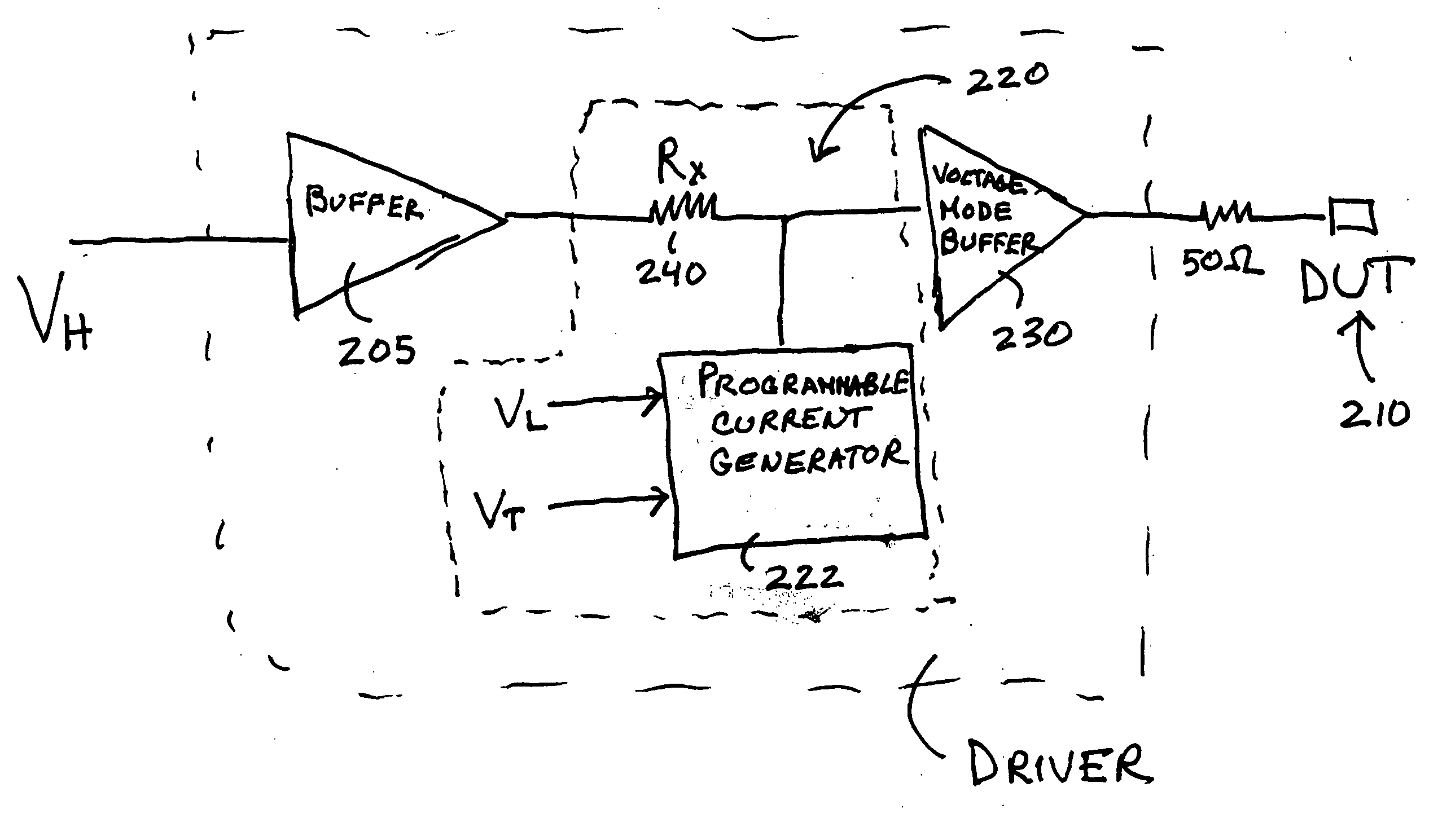
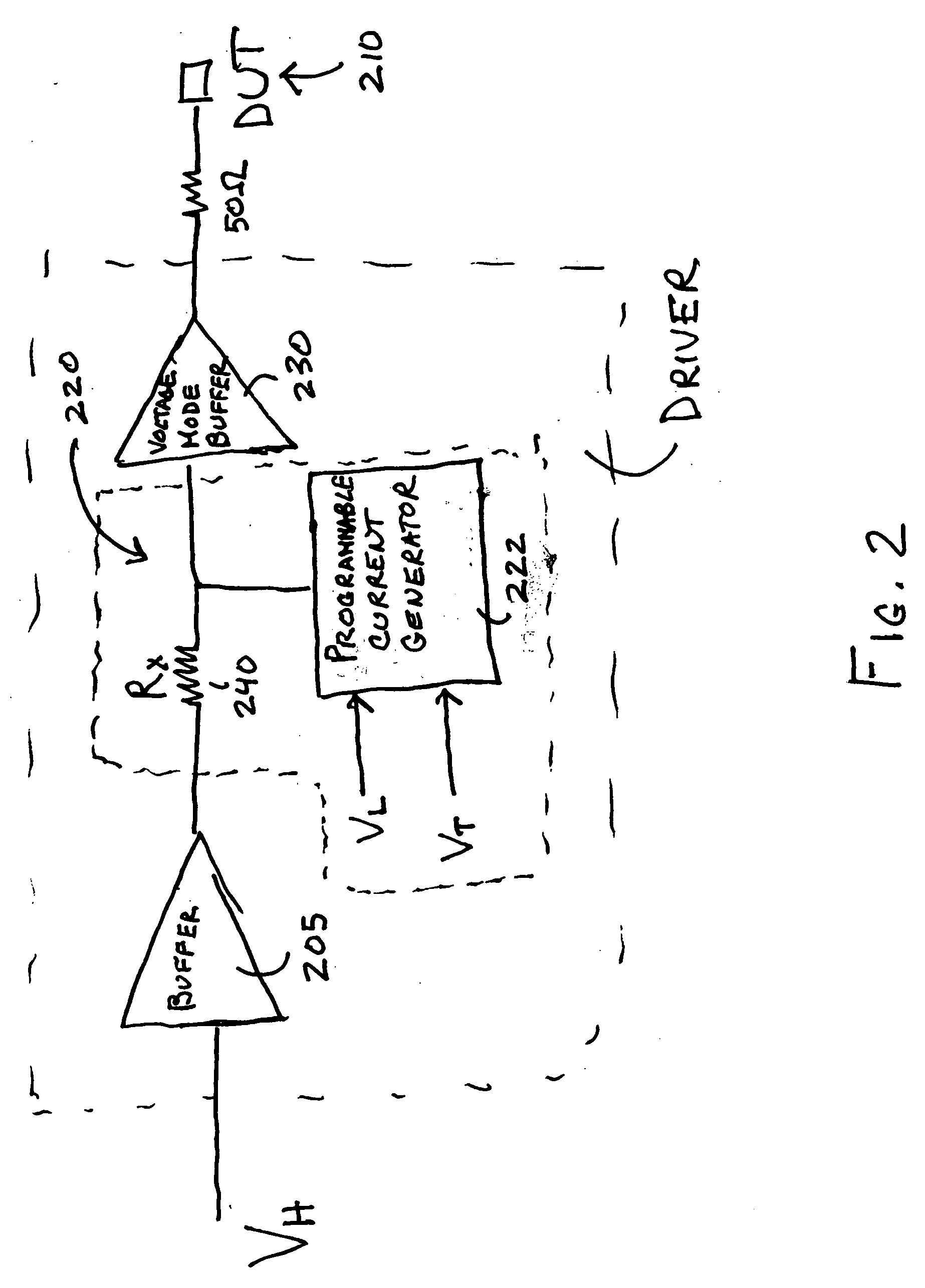
[0016]FIG. 2 is a block diagram of a first embodiment of the invention. The figure shows a driver circuit 200 coupled to a pin of a device under test (DUT) 210. A current mode waveform generator 220 generates a driver signal, for example Vh, Vt, or Vl. The current mode waveform generator includes a programmable current generator 222 that generates a current of programmable shape in the time domain and a resistor that receives the current creating a voltage waveform. Examples of current mode waveform generators include but are not limited to a class A linear amplifier as described in U.S. Pat. No. 6,677,775 and the KT-linear driver as described in U.S. patent application Ser. No. 10 / 946,483 filed Sep. 21, 2004 which are both incorporated herein by reference in their entirety. The waveform signal is provided to a voltage mode buffer 230 that is coupled to the pin of the DUT through a cable having an impedance. The impedance of the cable is generally 50ohms. In the embodiment that is s...


PUM


Abstract

A power saving circuit that creates a fast changing high resolution signal for testing of a pin of a device under test is disclosed. The circuit of the invention includes a current mode waveform generator followed by a voltage mode buffer. For example, the current mode waveform generator may be an A-linear or KT-linear stage. The voltage mode buffer may be a class AB output stage. By including the voltage mode buffer after the current mode waveform generator, the required standing power for the driver circuit is reduced when compared to using a current mode waveform generator alone.

Description

CROSS REFERENCE TO RELATED APPLICATIONS [0001] The present application claims priority from U.S. Provisional Patent Application No. 60 / 636,373 filed on Dec. 15, 2004, entitled “Class A Drive Architecture in Front of Classic AB Driver Output Stage,” which is incorporated herein by reference in its entirety.TECHNICAL FIELD AND BACKGROUND ART [0002] The present invention relates to drivers and more specifically to drivers for use in automatic testing equipment (ATE). It is known in the prior art to use class A-linear or KT-Linear stages for generating a voltage waveform and coupling such a stage to the pin of a device under test. Normally there is an associated 50 ohm load at the pin or wire that connects the driver stage to the device under test. The output resistance of the driver is preferably matched to this resistance. As such, these driver stages require large standing power due to the size of the current sources to produce Volt level voltage swings. [0003]FIG. 1 shows a prior ar...

Claims


Application Information

Patent Timeline
IPC IPC(8): G06F13/40
CPCG01R31/2841G01R31/31721G01R31/31924
Inventor HAIGH, GEOFFREYTURVEY, ANTHONY E.
Owner ANALOG DEVICES INC
Why Eureka
Try Eureka