
Computerized electroporation

a computerized electroporation technology, applied in the field of electroporation, can solve the problems of inability to control the electroporation equipment and different electroporation processes, the method is not suitable for use in the flow electroporation chamber, and the use of high or repetitive electric charges is not suitable for large volume of sample processing,

Active Publication Date: 2006-08-03
MAXCYTE
View PDF4 Cites 6 Cited by
  • Summary
  • Abstract
  • Description
  • Claims
  • Application Information

AI Technical Summary

Benefits of technology

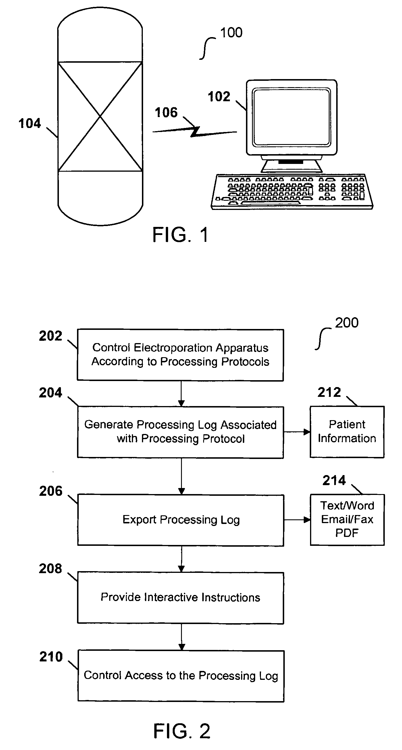
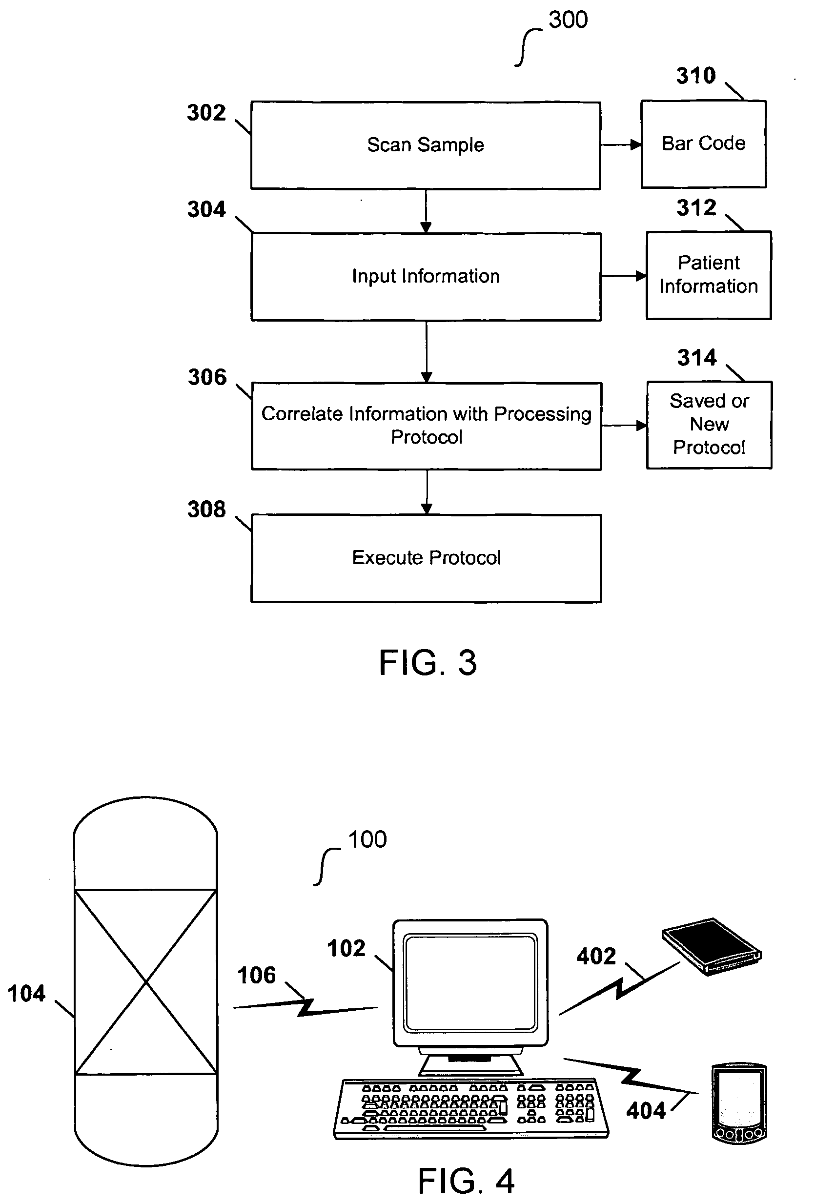
[0016] In another respect, the system involves a system including an electroporation apparatus and a particularly-configured computer. The electroporation apparatus is configured to subject a sample to electrical energy sufficient to effect electroporation. The computer is coupled to the electroporation apparatus and is configured to: (i) scan the sample to identify information assigned to the sample; (ii) input the information; (iii) correlate the information with a pre-existing, processing protocol; and (iv) execute the protocol to electroporate the sample.
[0017] In another respect, the invention involves a method in which an electroporation apparatus is controlled with a computer according to one of a plurality of previously-saved, user-defined processing protocols. A sample is subjected a to electrical energy sufficient to effect electroporation according to the previously-saved, user-defined processing protocol. The electroporation apparatus may be a flow electroporation apparatus, and the sample may be subjected to the electrical energy while the sample is flowing within the flow electroporation apparatus. The method may also include generating a processing log associated with a processing protocol, the processing log including patient or sample specific information. The method may also include exporting the processing log or a summary of the processing log in an encrypted format. The processing log may include a plurality of fields selected from the group consisting of: file, data, instrument identification, use number, protocol title, protocol description, protocol uses, protocol created, protocol last modified, processing chamber, access level, electrical information, electroporation equipment information, sample specific information, and patient information. The method may also include controlling access to the processing log according to a security level. The method may also include controlling access to the electroporation apparatus according to a security level and generating an audit trail that stores one or more activities of an authorized user. The method may also include providing interactive instructions to a user, the instructions corresponding to one or more steps of a processing protocol. The interactive instructions may include instructions for (i) checking hardware status of the flow electroporation apparatus or (ii) assembling or activating one or more components of the flow electroporation apparatus. The previously-saved, user-defined processing protocol may correspond to a processing protocol of a previous experiment. The method may also include determining if one or materials are validated for use with the electroporation apparatus and prohibiting use if one or more materials are not validated.

Problems solved by technology

Many electroporation methods disclosed in the art are not suitable for processing large volumes of sample, nor use of a high or repetitive electric charge.
Furthermore, the methods are not suitable for use in a flow electroporation chamber.
Regardless of the type of electroporation equipment being considered—flow or otherwise—the art does not make available advanced computerized techniques for controlling electroporation equipment and different electroporation processes.
Effective and meaningful integration of patient data into electroporation protocols and routines has been lacking.
Although relying on traditional techniques may provide suitable results, they are not ideal and leave room for improvement.
Referenced shortcomings of conventional methodologies mentioned above are not intended to be exhaustive, but rather are among several that tend to impair the effectiveness of previously known techniques concerning electroporation.
Other noteworthy problems may also exist; however, those mentioned here are sufficient to demonstrate that methodology appearing in the art has not been altogether satisfactory and that a significant need exists for the techniques described and claimed here.

Method used


Image

  • Computerized electroporation
  • Computerized electroporation
  • Computerized electroporation

Examples


examples

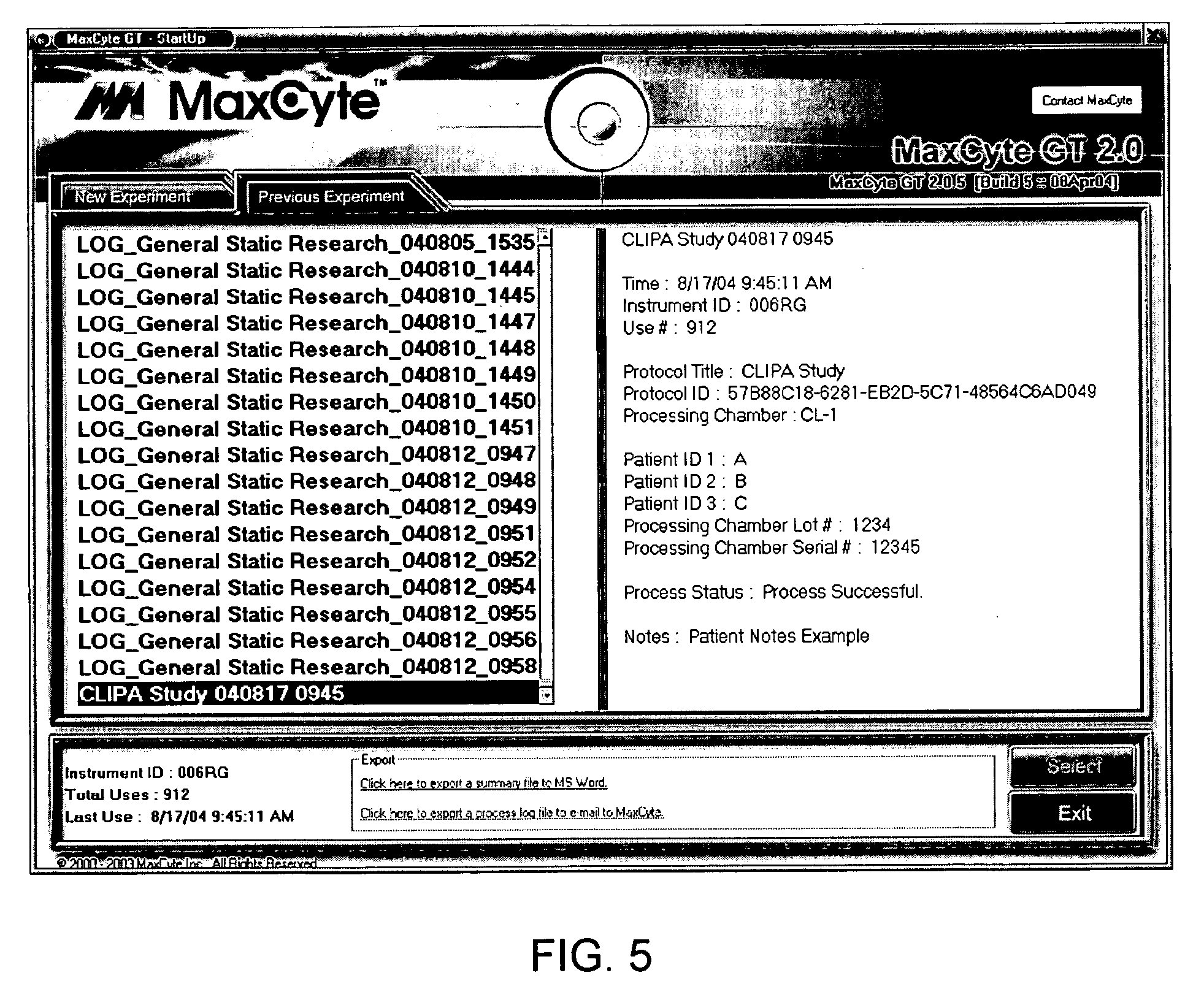
[0082]FIGS. 5-7 are example screen shots exhibiting computerized electroporation techniques, and particularly well suited for flow electroporation techniques, in accordance with embodiments of this disclosure.

[0083]FIG. 5 is a screen shot of a start up user interface. At the upper left are tabs for “Previous Experiment” and “New Experiment.” The Previous Experiment tab is selected in FIG. 5 and shows (in the window at left, under the tab) various experiments that correspond to different processing protocols. In one embodiment, different experiments may, however, be correlated with an identical processing log—for example, two experiments may have different names but may “call” the same underlying processing protocol.

[0084] In FIG. 5, the Previous Experiment entitled, “CLIPA Study 040817 0945” is highlighted. To the window at right, the software displays information about that experiment. This window is akin to a processing log display, showing at least some processing information a...


PUM

PropertyMeasurementUnit
electrical energyaaaaaaaaaa
processingaaaaaaaaaa
electric fieldaaaaaaaaaa

Abstract

Techniques for computerized electroporation. An electroporation apparatus may be controlled according to one of a plurality of previously-saved, user-defined processing protocols. A processing log associated with a processing protocol may be generated, and the processing log may include patient or sample specific information. The processing log or a summary of the processing log may be exported to a user. Interactive instructions may be provided to a user. Those instructions may correspond to one or more steps of a processing protocol.

Description

[0001] This application claims priority to, and incorporates by reference, U.S. Provisional Patent Application Ser. No. 60 / 631,751, which was filed on Nov. 30, 2004.BACKGROUND OF THE INVENTION [0002] 1. Field of the Invention [0003] The present invention relates generally to electroporation and flow electroporation. More particularly, it concerns software and other computer-related aspects of electroporation. [0004] 2. Description of Related Art [0005] The process of electroporation generally involves the formation of pores in cell membranes, or in any vesicles, by the application of an electric field. During a poration process, cells may be suspended in a liquid media and then subjected to an electric field pulse. The medium may be electrolyte, non-electrolyte, or a mixture of electrolytes and non-electrolytes. The strength of the electric field applied to the suspension and the length of the pulse (the time that the electric field is applied to a cell suspension) typically varies ...

Claims


Application Information

Patent Timeline
Patent Type & Authority Applications(United States)
IPC IPC(8): G06F19/00C12N15/87
CPCC12M35/02C12M41/48C12M1/42C12M3/00C12N15/10G06F15/76
Inventor DZEKUNOV, SERGEY M.WANG, SARAH H.HANSON, ARTHUR D.
Owner MAXCYTE
Learn More