White organic electroluminescence device
an electroluminescence device and white light technology, applied in the direction of luminescnet screens, discharge tubes, other domestic articles, etc., can solve the problems of short life of light emission and chromaticity tend to change, and achieve long life, no change in chromaticity, and great light emission efficiency
- Summary
- Abstract
- Description
- Claims
- Application Information
AI Technical Summary
Benefits of technology
Problems solved by technology
Method used
Image
Examples
example 1
Preparation of an Organic EL Device of the Laminate Type having a Portion of a Light Emitting Layer Emitting Blue Light / a Light Emitting Layer Emitting Yellow Light
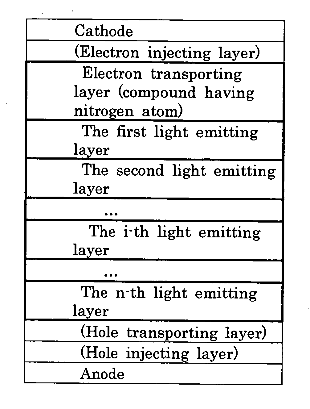
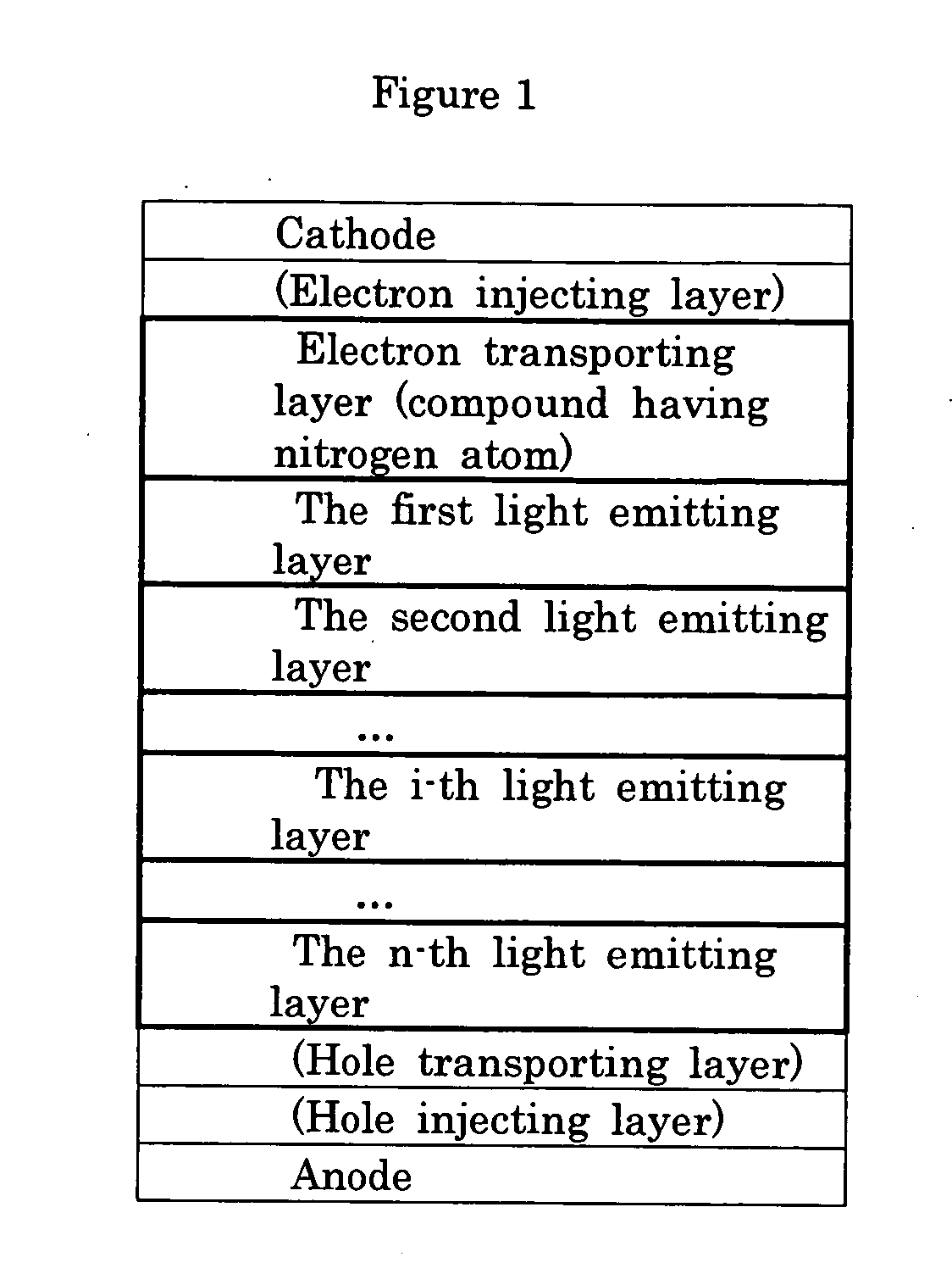
[0124] A glass substrate of 25 mm×75 mm×1.1 mm thickness having an ITO transparent electrode (manufactured by GEOMATEC Company) was cleaned by application of ultrasonic wave in isopropyl alcohol for 5 minutes and then by exposure to ozone generated by ultraviolet light for 30 minutes. The cleaned glass substrate having the transparent electrode was attached to a substrate holder of a vacuum vapor deposition apparatus. On the surface of the cleaned substrate at the side having the transparent electrode, a film of N,N′-bis(N,N′-diphenyl-4-aminophenyl)-N,N-diphenyl-4,4′-diamino-1,1′-biphenyl (referred to as “TPD232”, hereinafter) having a thickness of 60 nm was formed in a manner such that the formed film covered the transparent electrode. The formed TPD232 film worked as the hole injecting layer. On the formed TPD232 film,...
example 2
Preparation of an Organic EL Device of the Laminate Type having a Portion of a Light Emitting Layer Emitting Blue Light / a Light Emitting Layer Emitting Yellow Light / a Light Emitting Layer Emitting Blue Light
[0126] An organic EL device emitting white light was prepared in accordance with the same procedures as those conducted in Example 1 except that the light emitting layers were prepared as described in the following.
[0127] On the TBTB film, DPVDPAN (Ip=5.7 eV; Eg=3.0 eV) as the styryl derivative and Compound B1 shown above (the peak of light emission: 470 nm; Ip=5.5 eV; Eg=2.8 eV) as the dopant compound were vapor deposited simultaneously to form a film having a thickness of 10 nm in which the ratio of the thickness of the DPVDPAN film to the thickness of the Compound B1 film was 40:2. The formed film was used as the first light emitting layer (the light emitting layer emitting blue light). Then, DPVDPAN (Ip=5.7 eV; Eg=3.0 eV) as the styryl derivative and Compound R1 shown above...
example 3
Preparation of an Organic EL Device of the Laminate Type having a Portion of a Light Emitting Layer Emitting Yellow Light / a Light Emitting Layer Emitting Blue Light / a Light Emitting Layer Emitting Yellow Light
[0129] An organic EL device emitting white light was prepared in accordance with the same procedures as those conducted in Example 1 except that the light emitting layers were prepared as described in the following.
[0130] On the TBTB film, DPVDPAN (Ip=5.7 eV; Eg=3.0 eV) as the styryl derivative and Compound R1 shown above (the peak of light emission: 560 nm; Ip=5.6 eV; Eg=2.6 eV) as the dopant compound were vapor deposited simultaneously to form a film having a thickness of 10 nm in which the ratio of the thickness of the DPVDPAN film to the thickness of the Compound R1 film was 40:2. The formed film was used as the first light emitting layer (the light emitting layer emitting yellow light). Then, DPVDPAN (Ip=5.7 eV; Eg=3.0 eV) as the styryl derivative and Compound B1 shown a...
PUM
| Property | Measurement | Unit |
|---|---|---|
| energy gap | aaaaa | aaaaa |
| peak wavelength | aaaaa | aaaaa |
| work function | aaaaa | aaaaa |
Abstract
Description
Claims
Application Information
 - R&D
- Intellectual Property
- Life Sciences
- Materials
- Tech Scout
- Unparalleled Data Quality
- Higher Quality Content
- 60% Fewer Hallucinations
Browse by: Latest US Patents, China's latest patents, Technical Efficacy Thesaurus, Application Domain, Technology Topic, Popular Technical Reports.
© 2025 PatSnap. All rights reserved.Legal|Privacy policy|Modern Slavery Act Transparency Statement|Sitemap|About US| Contact US: help@patsnap.com


