
Side view LED package having lead frame structure designed to improve resin flow

a technology of led package and lead frame structure, which is applied in the direction of steering rudder, semiconductor device details, semiconductor/solid-state device details, etc., can solve the problems of reducing the thickness of the wall part, unable to ensure reliability, weakening the wall strength, etc., and achieve the effect of improving the resin flow

Active Publication Date: 2006-08-03
SAMSUNG ELECTRONICS CO LTD
View PDF2 Cites 41 Cited by
  • Summary
  • Abstract
  • Description
  • Claims
  • Application Information

AI Technical Summary

Benefits of technology

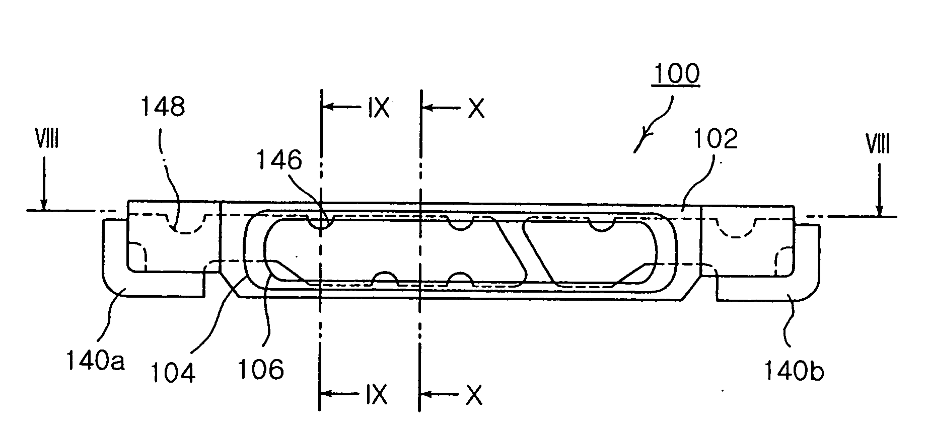
The present invention provides a side view LED package with a lead frame structure designed to improve resin flow and ensure stability even if the LED package is made extremely thin. The lead frame structure includes a toothed structure formed in a lateral edge of the lead frame, which promotes resin to flow from the rear half to the front half of the package body. The toothed structure may also include a groove or hole that is fully buried in the package body or a remaining part of the lead frame in the cavity stably supports the lead frame. The toothed structure may be formed by punching or by a combination of punching and other methods. The technical effects of the invention include improved resin flow and stability of the LED package under high temperature-induced stress.

Problems solved by technology

However, reducing the wall part thickness is extremely difficult task.
This task also potentially weakens wall strength thereby failing to ensure reliability.
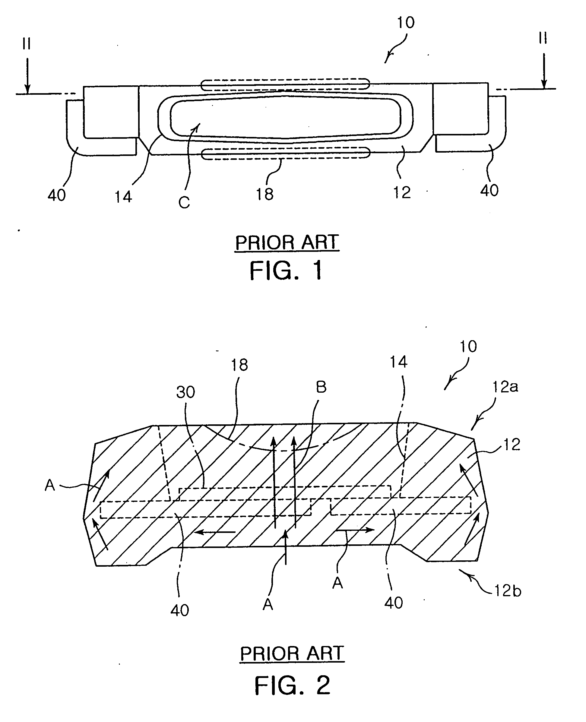
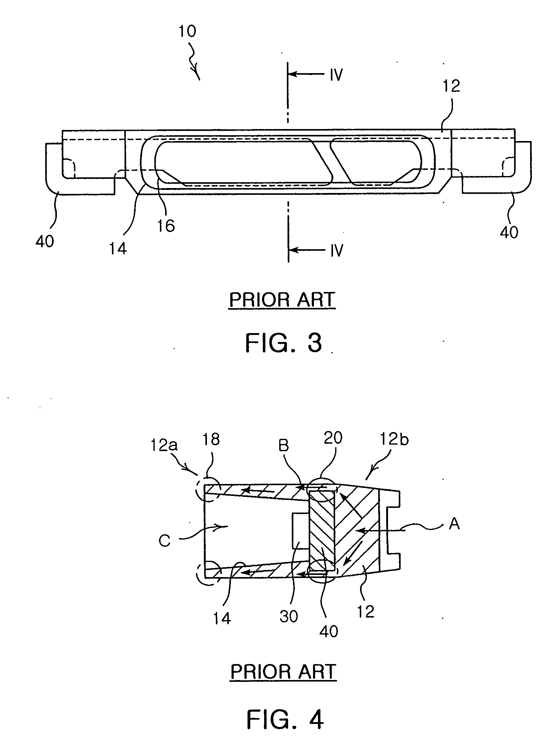
Therefore, it is apparent that resin does not smoothly flow along the direction of arrow B.
Then, resin insufficiently feeds to central leading ends of the upper and lower wall parts 18, thereby creating molding defects such as V-shaped voids.
In particular, since the LED package is getting longer in reverse proportion to its thickness reduction, the central leading ends of the wall parts 18 become more susceptible to molding defects.
These problems are getting more serious according to the reduced thickness of the LED package 10 accompanied with its increased length.

Method used


Image

  • Side view LED package having lead frame structure designed to improve resin flow
  • Side view LED package having lead frame structure designed to improve resin flow
  • Side view LED package having lead frame structure designed to improve resin flow

Examples


Embodiment Construction

[0036] Hereinafter preferred embodiments of the present invention will be described in detail with reference to the accompanying drawings.

[0037]FIG. 6 is a plan view illustrating lead frames of the invention, which are not mounted on an LED package.

[0038] Referring to FIG. 6, a pair of lead frames 140a and 140b according to a preferred embodiment of the invention shown in a plan view. The lead frames 140a and 140b are spread before being inserted into a mold to produce an LED package. When the lead frames 140a and 140b are inserted into the mold, external terminals 144 are folded about internal terminals 142.

[0039] The first and second lead frames 140a and 140b have a toothed configuration. That is, first resin flowing grooves 146 in the shape of semicircle are formed at both lateral edges of the strip-shaped internal terminal 142 of the first lead frame 140a, and a first resin flowing groove 146 in the same shape is formed at one lateral edge of the strip-shaped internal termina...


PUM


Abstract

The invention relates to a side view LED package in use with an LCD backlight unit. The side view LED package comprises: an LED chip; and a strip-shaped lead frame having a toothed structure formed in a lateral edge thereof. The LED chip is mounted on a surface of the lead frame. An integral package body is made of resin, and includes a hollow front half having a cavity for housing the LED chip and a solid rear half divided from the front half by the lead frame. The toothed structure of the lead frame structure can improve resin flow in order to ensure stability even if the LED package is made extremely thin.

Description

CLAIM OF PRIORITY [0001] This application claims the benefit of Korean Patent Application No. 2005-8218 filed on Jul. 28, 2005, in the Korean Intellectual Property Office, the disclosure of which is incorporated herein by reference. BACKGROUND OF THE INVENTION [0002] 1. Field of the Invention [0003] The present invention relates to a side view Light Emitting Diode (LED) package in use with an LCD backlight unit. More particularly, the invention relates to a side view LED package having a lead frame structure designed to improve resin flow in order to ensure stability even if the LED package is made extremely thin. [0004] 2. Description of the Related Art [0005] Side view LEDs are widely used as a light source of a backlight unit of a small-sized LCD in a mobile phone, a Personal Digital Assistant (PDA) and so on. The side view LEDs are used in a package, in which their mounting height is getting gradually reduced and it is expected that a dimension of 0.5 mm or less will be required...

Claims


Application Information

Patent Timeline
Patent Type & Authority Applications(United States)
IPC IPC(8): H01L23/495H01L33/22H01L33/56H01L33/62
CPCH01L33/486H01L33/62H01L2924/0002H01L2924/00B63H25/08
Inventor KIM, CHANG WOOKSONG, YOUNG JAE
Owner SAMSUNG ELECTRONICS CO LTD
Learn More