
Method for etching a sample and etching system

Inactive Publication Date: 2006-08-03
MICRONAS
View PDF8 Cites 0 Cited by
  • Summary
  • Abstract
  • Description
  • Claims
  • Application Information

AI Technical Summary

Benefits of technology

[0010] Retaining these determined setting parameters, the inert gas is then fed through the reaction chamber instead of the reactive gas, to stabilize the process. After switching to the reactive gas mixture while retaining all of the setting parameters, the plasma can be ignited immediately without any time delay.
[0011] The invention has the advantage that the setting parameters and thus the process are stabilized by an economical and environmentally harmless inert gas. For these reasons, the costs of etching are considerably reduced and environmental pollution is also considerably reduced.

Problems solved by technology

However, unutilized reactive gas is blown through the reactive chamber into the open with each reset.
It is a drawback to this method that considerable amounts of expensive and frequently also environmentally harmful reactive gases are necessary for resetting the process parameters and are then blown into the open.

Method used


Image

  • Method for etching a sample and etching system
  • Method for etching a sample and etching system

Examples


Embodiment Construction

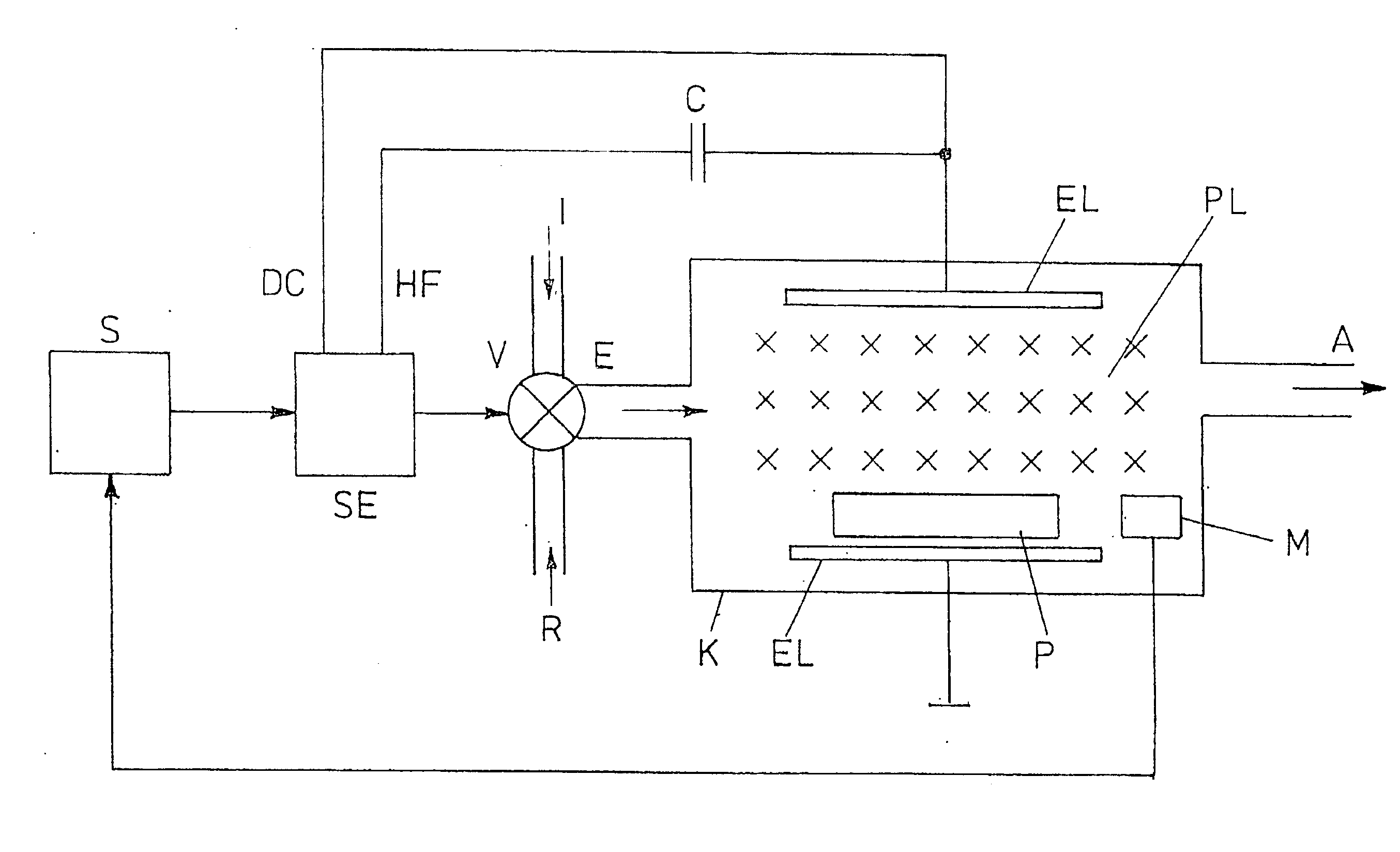
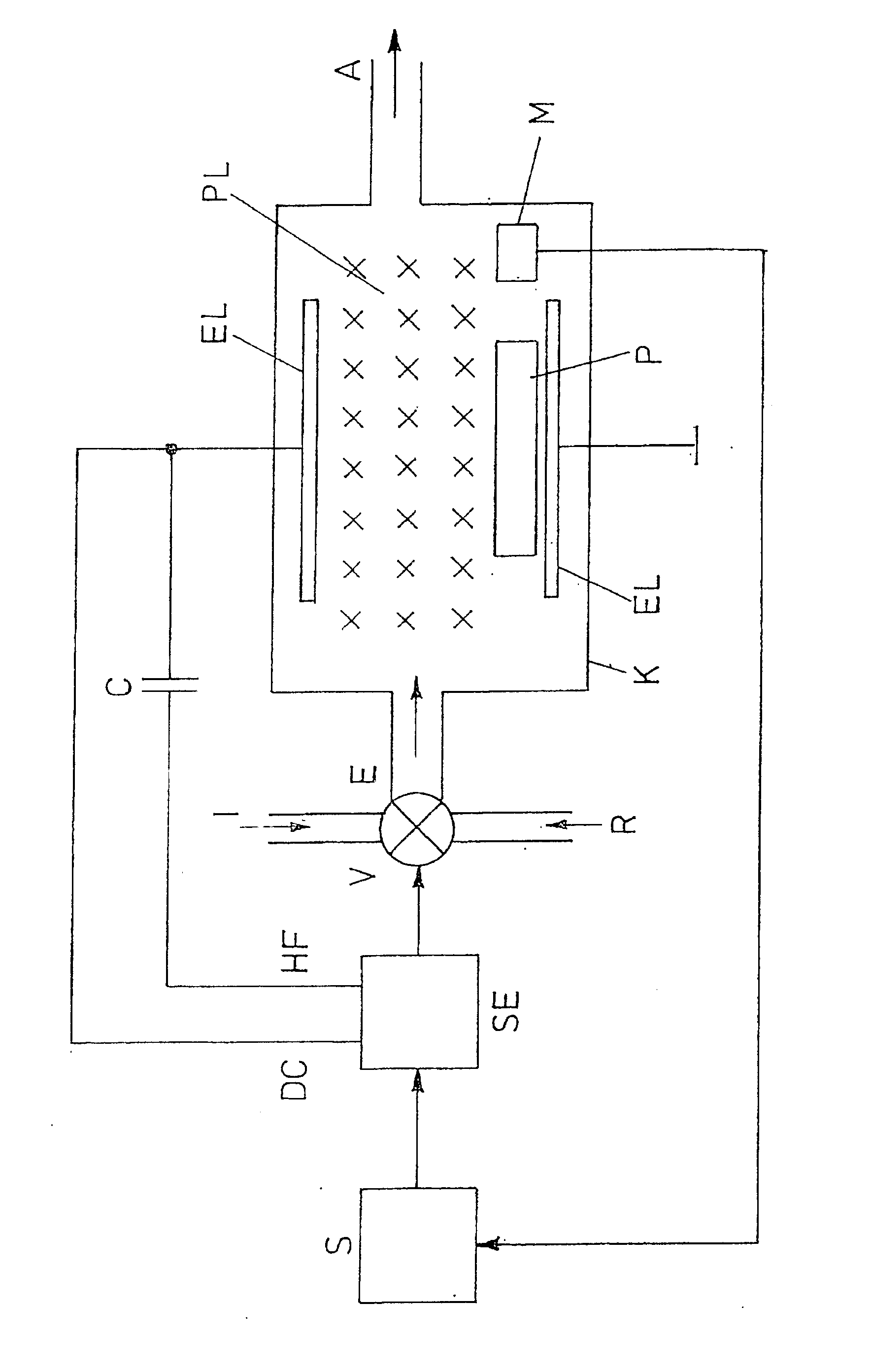
[0015] In a reaction chamber, the sample 100 to be etched is positioned between two electrodes 102, 104. A first output on a line 108 of a control unit provides a high d.c. voltage to the first electrode 102, while the other electrode 104 is grounded. A second output of the control unit 106 on a line 110 provides a high-frequency high voltage signal that through a capacitor 112 to the first electrode 102. A control output on a line 114 from the control unit 106 is connected to a control valve 116 to which the inert gas 118 and the reactive gas 120 are connected. Either the inert gas 118 or the reactive gas mixture 120 is fed from the control valve 116 through an inlet orifice 122 into a reaction chamber 124, which has an outlet orifice 126 for gas discharge. A measuring sensor 128, for example, is located in the reaction chamber 124 to detect the process parameters. The measuring sensor 128 provides a sensed signal on a line 130 to a memory 132 to store the process and setting param...


PUM

PropertyMeasurementUnit
Flow rateaaaaaaaaaa

Abstract

To reduce the use of expensive reactive gas, which is frequently also environmentally harmful, during etching by a plasma the reactive gas is first fed through a reaction chamber of an etching system for stabilization, until all the process parameters are adjusted to their setpoints. During this stabilization, all of the setting parameters of the etching system are stored in a memory. After storage, the gas flow rate of an inert gas, for example helium, that is fed through the reaction chamber instead of reactive gas is raised from an initial value until the reference gas flow rate is found that causes the same setting parameters as the reactive gas. This reference gas flow rate is also stored in the memory. In each subsequent etching process, the etching system is first adjusted by the inert gas flowing through the reaction chamber with the determined reference gas flow rate, and after stabilization is complete, the reactive gas is fed through the reaction chamber and the plasma is ignited for the actual etching process.

Description

PRIORITY INFORMATION [0001] This patent application claims priority from PCT application PCT / EP2004 / 002411 filed Mar. 9, 2004, which claims the benefit of German patent application DE 103 10 524.7 filed Mar. 11, 2003. BACKGROUND OF THE INVENTION [0002] The invention relates to the field of semiconductor manufacturing, and in particular to a system and method for etching of a semiconductor. [0003] Etching methods are used, for example, in the production of semiconductor chips. A mask is placed on a layer, for example consisting of silicon, of a semiconductor. The surfaces of the layer not protected by the mask are etched by a plasma, because the plasma is able to transform the material to be etched into the gas phase. [0004] In an etching system, the sample, for example a multilayered system of multiple layers, is located in a reaction chamber with an inlet orifice for gas infeed and with an outlet orifice for gas discharge. At the beginning of the etching process, a reactive gas mix...

Claims


Application Information

Patent Timeline
IPC IPC(8): G01L21/30C23F1/00H01L21/306C23F4/00H01J37/32
CPCH01J37/32449H01J2237/3341
Inventor FOEH, DENNIS
Owner MICRONAS
Learn More