Confocal probe and endoscope device
a confocal probe and endoscope technology, applied in the field of confocal probe and endoscope device, can solve the problems of difficult rapid application of medical treatment, large sensitivity of endoscope, and large sensitivity of endoscope, and achieve the effect of simple manufacturing and assembly process, excellent thermal characteristics, and small diameter of confocal prob
- Summary
- Abstract
- Description
- Claims
- Application Information
AI Technical Summary
Benefits of technology
Problems solved by technology
Method used
Image
Examples
first embodiment
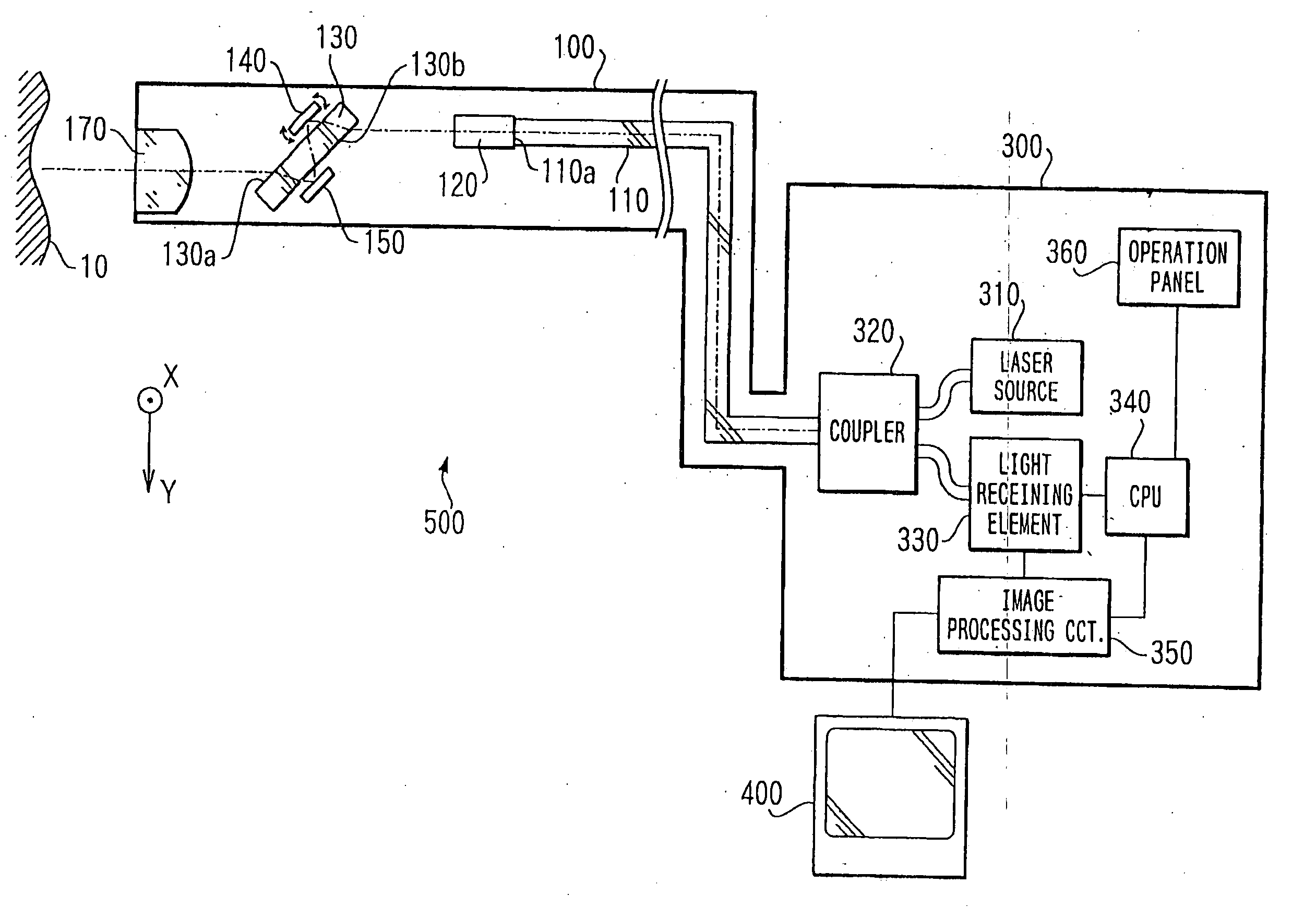
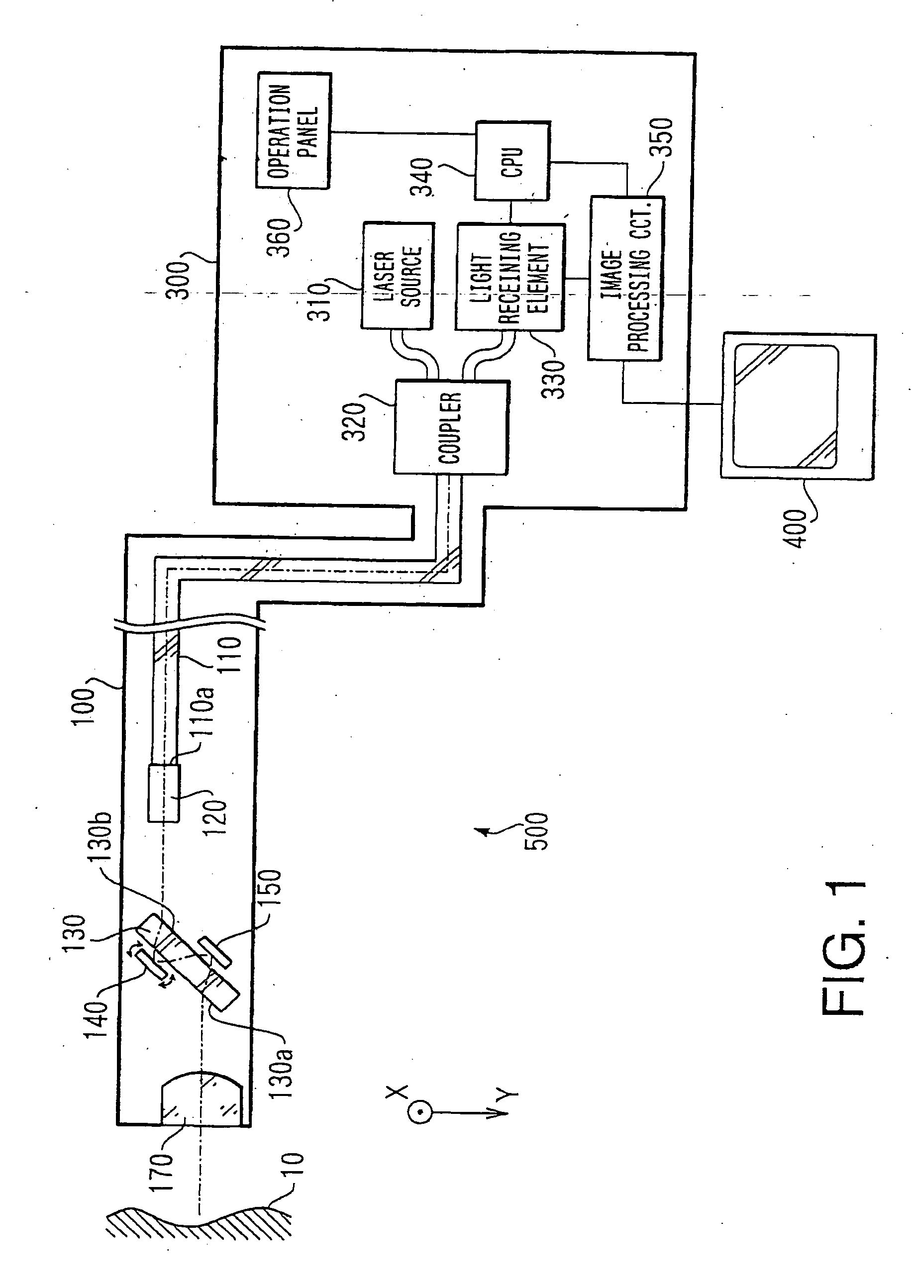
[0032]FIG. 1 shows a block diagram of a scanning type confocal probe device 500 according to the invention. The confocal probe device 500 includes a scanning type confocal probe unit 100, a processing unit 300 and a monitor 400.
[0033] The confocal probe unit 100 is inserted in a forceps channel of an endoscope (not shown), which is inserted in a human cavity. An image inside the human cavity (e.g., tissues) can be captured using the probe unit 100. The captured image is processed by the processing unit 300 and is displayed on the monitor 400.
[0034] As shown in FIG. 1, the processing unit 300 includes a laser source 310, a coupler 320, a light receiving element 330, a CPU (Central Processing Unit) 340, an image processing circuit 350 and an operation panel 360.
[0035] The laser source 310 according to the first embodiment emits an He—Ne laser having a wavelength of 421 nm. It is known that the shorter the wavelength of the laser beam is, the higher the resolution of the image is. It...
second embodiment
[0057]FIG. 3 is a block diagram showing a confocal probe device 500y according to the invention. In FIG. 3, the elements identical to those shown in FIG. 1 are given the same reference numerals, and description thereof will not be repeated.
[0058] The confocal probe device 500y includes a confocal probe unit 100y, the processing unit 300 and the monitor 400.
[0059] According to the confocal probe device 500y, only one micromirror is used to obtain a two-dimensional image of the tissues. In the confocal probe device 500y, a two-axis scanning type (which is capable of deflecting the laser beam both in the X direction and in the Y direction) micromirror 150y is employed instead of the second micromirror 150 of the first embodiment. Further, the first micromirror 140 of the first embodiment is replaced with a mirror (e.g., a single metal layer or multilayer coating of dielectric substance) 140y.
[0060] It should be noted that, in the structure shown in FIG. 3, the mirror 140y is formed o...
third embodiment
[0061]FIG. 4 is a block diagram showing a confocal probe device 500z according to the invention. In FIG. 4, the elements identical to those shown in FIG. 1 are given the same reference numerals, and description thereof will not be repeated.
[0062] As shown in FIG. 4, the confocal probe device 500z includes a confocal probe unit 100z, a processing unit 300z and the monitor 400.
[0063] The processing unit 300z includes a laser source 310z, having a Brewster window, through which polarized beam is emitted. The beam emerged from the Brewster window is an S-polarized beam with respect to a polarization layer 181, which will be described later.
[0064] The laser beam emitted by the laser source 310Z is incident on the optical fiber 110 of the confocal probe unit 100z through the coupler 320. The light beam transmitted through the optical fiber 110 is collimated by the GRIN lens 120 and is introduced to a polarization beam splitting cube 180.
[0065] The polarization beam splitting cube 180 h...
PUM
 Abstract
Description
Claims
Application Information
 - R&D Engineer
- R&D Manager
- IP Professional
- Industry Leading Data Capabilities
- Powerful AI technology
- Patent DNA Extraction
Browse by: Latest US Patents, China's latest patents, Technical Efficacy Thesaurus, Application Domain, Technology Topic, Popular Technical Reports.
© 2024 PatSnap. All rights reserved.Legal|Privacy policy|Modern Slavery Act Transparency Statement|Sitemap|About US| Contact US: help@patsnap.com


