
Image pickup apparatus, camera main body thereof and interchangeable lens

Inactive Publication Date: 2006-07-27
CANON KK
View PDF3 Cites 45 Cited by
  • Summary
  • Abstract
  • Description
  • Claims
  • Application Information

AI Technical Summary

Benefits of technology

[0022] So, it is the object of the present invention to provide an image pickup apparatus and a lens-interchangeable camera system which quickly effect the stabilization of a parallel vibration detection signal during a framing change, and which are also effective for vibration correction during macro-photographing.
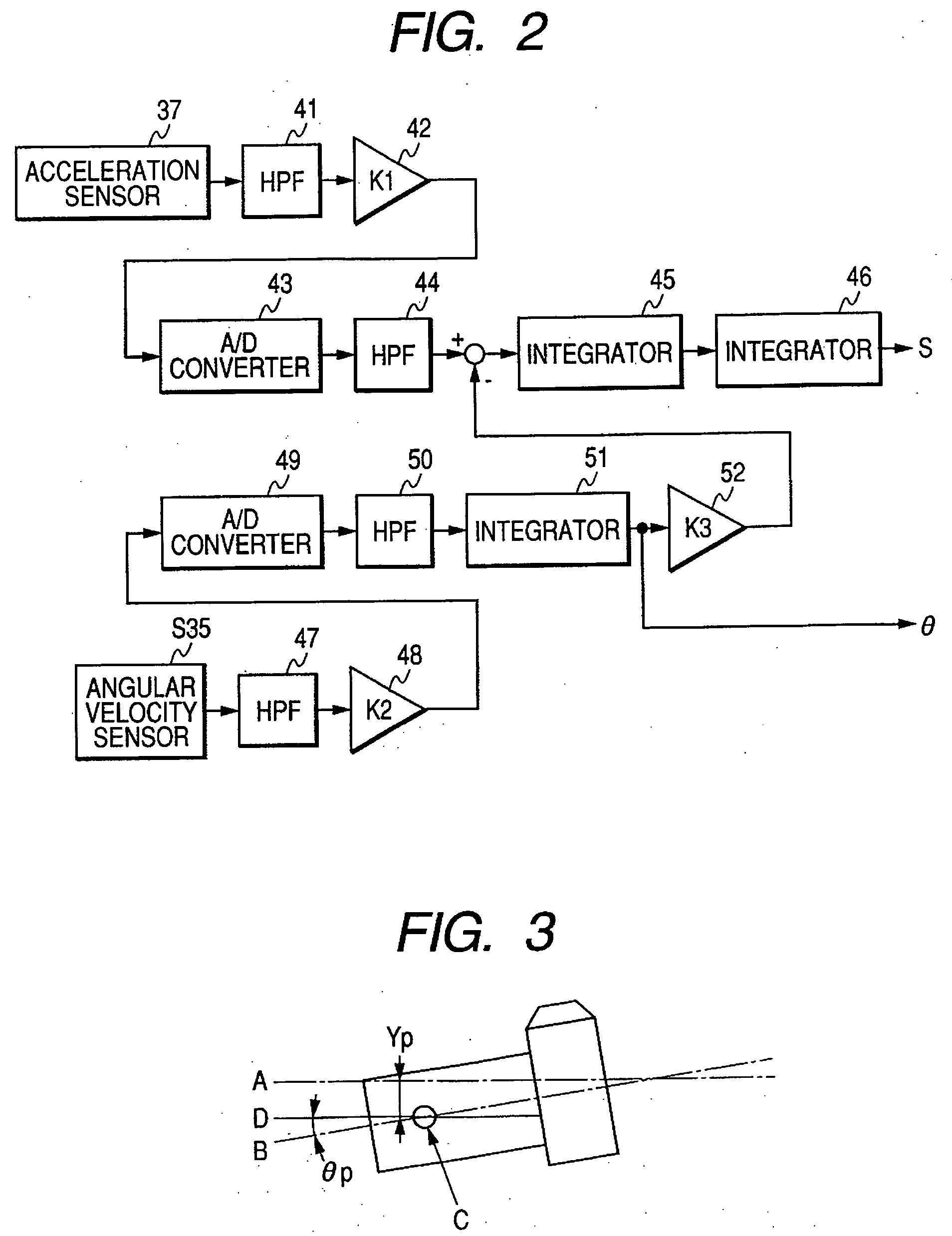
[0024] Thereby, any change in the gravity acceleration component of the acceleration sensor due to a change in framing can be quickly eliminated, and the stabilization of the parallel vibration detection signal can be effected quickly. As the result, accurate image blur correction can be accomplished.

Problems solved by technology

In the present day cameras, operations important to photographing such as exposure determination and focusing are all automated and the possibility that even a person unskilled in camera operation causes failure in photographing has become very rare.
Also, recently, a system for preventing a hand shake applied to a camera has also been studied, and factors inducing a photographer's error in photographing has become almost null.
It results in the necessity of the larger scale and increased cost of the system, and a high-speed calculation processing system.

Method used


Image

  • Image pickup apparatus, camera main body thereof and interchangeable lens
  • Image pickup apparatus, camera main body thereof and interchangeable lens
  • Image pickup apparatus, camera main body thereof and interchangeable lens

Examples


first embodiment

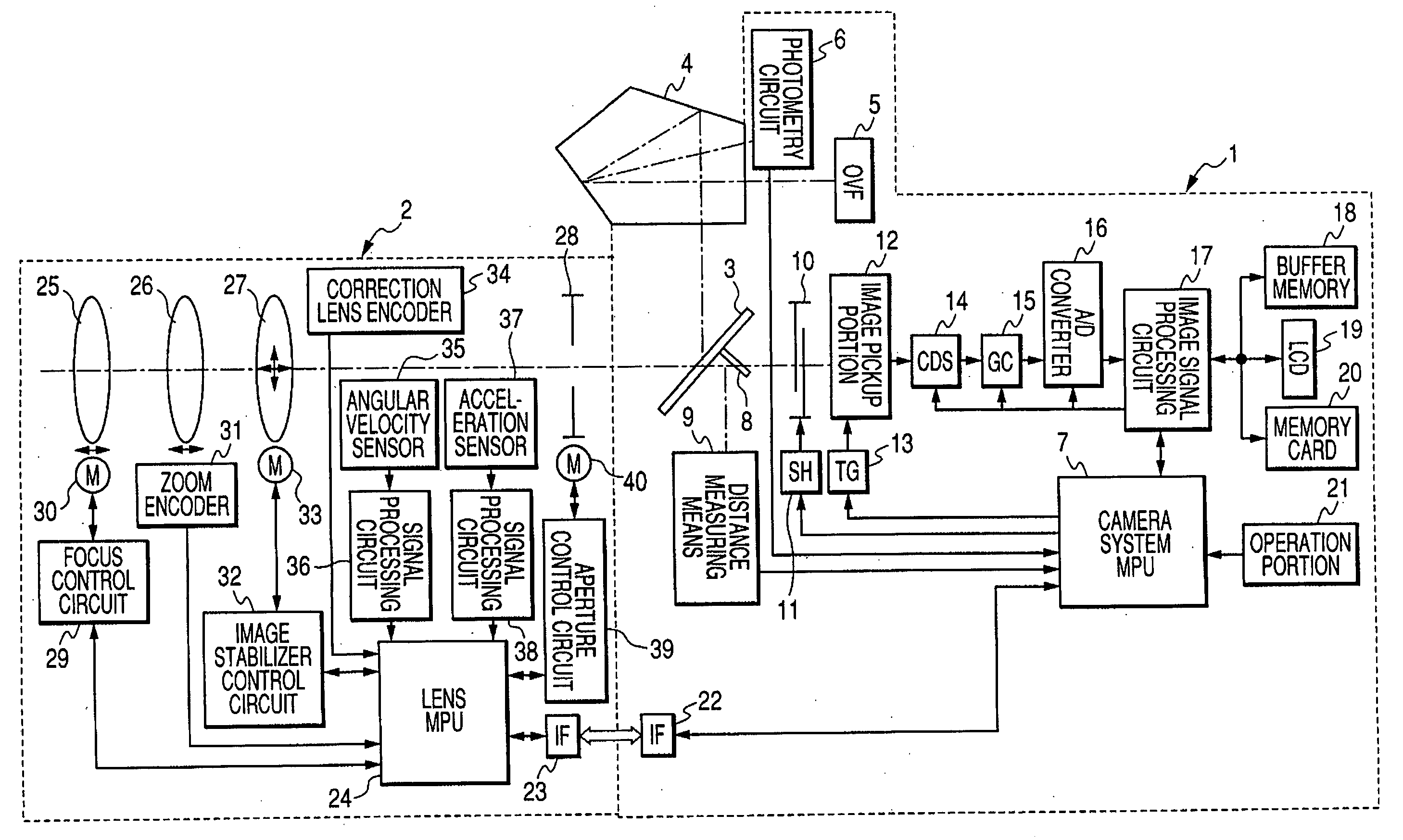
[0037]FIG. 1 shows a camera system comprising a camera main body 1 and an interchangeable lens 2.

[0038] A photographing light beam from an object to be photographed passes through the photo-taking optical system of the interchangeable lens 2, and a part thereof is reflected by the quick return main mirror 3 of the camera main body 1 of which the central portion provides a half mirror during the preparation for photographing.

[0039] Thereafter, the light beam becomes an erect image in a penta-prism 4, and a photographer can confirm it as an object image through an optical viewfinder (OVF) 5.

[0040] Also, the reference numeral 6 designates a photometry circuit which measures the illuminance on the surface of a focusing plate, not shown, and inputs the result of the measurement to a camera system control MPU 7.

[0041] On the basis of the result of the aforementioned measurement, photographing conditions such as an exposure time and an aperture are determined by the camera system contr...

second embodiment

[0172] A second embodiment of the present invention will now be described in detail. The construction of this embodiment is similar to that of the first embodiment shown in FIG. 1, and need not be described.

[0173] In the second embodiment, when the photographed image magnification β is smaller than a predetermined value, the cut-off frequency of the high-pass filter for the acceleration sensor signal processing is not changed.

[0174] When β is a predetermined value or greater, the cut-off frequency of the high-pass filter of the acceleration sensor signal processing portion for parallel vibration detection is heightened in conformity with the level of the rotation vibration angular velocity signal.

[0175] The operation of the interchangeable lens 2 side will now be described with reference to a flow chart shown in FIG. 8.

[0176] The operation of main portions are shown at steps 501 to 503, and the operations of the other portions are similar to those in the first embodiment and the...


PUM


Abstract

The present invention provides a camera system which is provided with signal processing control means for changing the filter characteristic of parallel vibration signal processing means in conformity with the output signal of rotation vibration signal processing means and thereby can photograph an image suffering little from blur even during macro-photographing.

Description

BACKGROUND OF THE INVENTION [0001] 1. Field of the Invention [0002] This invention relates to an image pickup apparatus which corrects hand shake to thereby improve the accuracy of a picked-up image, the camera main body thereof and an interchangeable lens. [0003] Particularly it relates to an image pickup apparatus which achieves an improvement in correcting performance for hand shake, the camera main body thereof and an interchangeable lens. [0004] 2. Related Background Art [0005] In the present day cameras, operations important to photographing such as exposure determination and focusing are all automated and the possibility that even a person unskilled in camera operation causes failure in photographing has become very rare. [0006] Also, recently, a system for preventing a hand shake applied to a camera has also been studied, and factors inducing a photographer's error in photographing has become almost null. [0007] An image stabilizer system for preventing hand shake will be br...

Claims


Application Information

Patent Timeline
IPC IPC(8): G03B17/00
CPCG03B5/00H04N5/23248H04N5/23287H04N23/68H04N23/687G03B17/14H04N23/55H04N23/681H04N23/682
Inventor IMADA, SHINJI
Owner CANON KK
Learn More