Rubber cup protection structure of rubber-cup-type stand pipe pressure sensor

A standpipe pressure and protection structure technology, applied in the direction of measuring fluid pressure, instruments, measuring devices, etc., can solve the problems of easy access, damage to pressure gauges, tearing of rubber cups, etc., to prolong life, reduce instantaneous impact, and install convenient effect

Inactive Publication Date: 2016-04-27
HUBEI JIANGHAN GASOLINEEUM INSTR & METER
View PDF8 Cites 0 Cited by
  • Summary
  • Abstract
  • Description
  • Claims
  • Application Information

AI Technical Summary

Problems solved by technology

[0003] Figure 4 It is the structural diagram of the plastic cup riser pressure sensor before improvement, Figure 5 It is a schematic diagram of the working of the rubber cup standpipe pressure sensor before improvement. Its disadvantage is that when the mud pressure in the rubber cup is too high and the pressure transmission medium is lacking, the stretching and expansion of the rubber cup can easily enter the oil hole at the bottom of the cylinder and block it. The pressure transmission hole is blocked, causing the rubber cup to tear, the mud is poured into the pressure transmission pipeline, and the pressure gauge is damaged

Method used


Image

  • Rubber cup protection structure of rubber-cup-type stand pipe pressure sensor
  • Rubber cup protection structure of rubber-cup-type stand pipe pressure sensor
  • Rubber cup protection structure of rubber-cup-type stand pipe pressure sensor

Examples


Embodiment Construction

[0017] The present invention is described in detail below in conjunction with accompanying drawing:

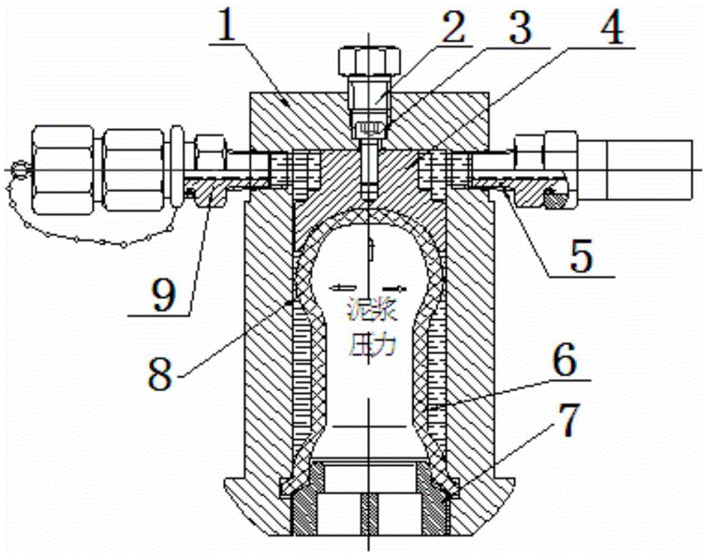
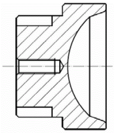
[0018] Such as figure 1 As shown, the present invention includes a cylinder bottom liner 4, a fastening screw 3 and a plug 2, and is characterized in that: the cylinder bottom liner 4 is fixed on the bottom of the cylinder body 1 by the fastening screw 3, and the raw material is tightly wound on the plug 2 The band plugs the cylinder block 1 bottom hole. Such as Figure 3a , Figure 3b As shown, one end of the cylinder liner 4 is a bowl-shaped concave curved surface, which is the same shape as the bottom of the rubber cup 6, and can support the rubber cup 6. When the rubber cup 6 expands, it is evenly stressed and is not easy to break. 4. The other end is a plane with a threaded hole, which is fastened to the bottom plate of the cylinder body 1 by bolts and will not loosen in the cylinder body 1.

[0019] The outer diameter of the cylinder liner 4 is smaller than the inne...


PUM


Abstract

The invention relates to a rubber cup protection structure of a rubber-cup-type stand pipe pressure sensor. The structure comprises a cylinder bottom pad, a fastening screw and a screwed plug. The structure is characterized in that the cylinder bottom pad is fixedly arranged to the bottom portion of a cylinder body through the fastening screw; and the screwed plug is plugged in a bottom hole in the cylinder body. The cylinder bottom pad is the main component of the structure, is used for protecting a rubber cup and is characterized in that the external diameter of the cylinder body is smaller than the inner diameter of the cylinder body by 0.5-1 mm, and the gap between the cylinder bottom pad and the inner wall of the cylinder body forms an annular pressure transmission space, so that the cylinder bottom pad is prevented from being provided with a pressure transmission hole, and the rubber cup is protected from being cut by coarse sharp-edged metal during expansion thereof under stress; besides, one end of the cylinder bottom pad is a bowl-shaped downwardly-concave curved surface, which is of the same shape with the bottom of the rubber cup, so that when the rubber cup expands, the cylinder bottom pad can hold the rubber cup to enable the rubber cup to be uniformly stressed and not to break easily; and the other end of the cylinder bottom pad is plane and is provided with a threaded hole, so that the cylinder bottom pad can be fixedly arranged to the plane at the tail end in the cylinder body and the cylinder bottom pad does not loosen in the cylinder body.

Description

technical field [0001] The invention relates to a rubber cup type riser pressure sensor, in particular to a rubber cup protection structure of the rubber cup type riser pressure sensor. Background technique [0002] Standpipe pressure is a drilling parameter that needs to be measured during oil drilling or workover operations. The mud pressure in the standpipe acts on the pressure transmission medium through the rubber cup in the sensor, and the pressure transmission medium transmits the pressure of the standpipe to the display meter. At present, the plastic cup standpipe pressure sensor widely used in the oil drilling industry has a large instantaneous change in working pressure, and the plastic cup used for pressure transmission is prone to swell and crack, resulting in mud entering the pressure transmission pipeline, damaging the display meter, and frequent replacement. Plastic cups bring inconvenience to drilling operations. Therefore, it is necessary to design a stand...

Claims


Application Information

Patent Timeline
IPC IPC(8): G01L19/06E21B47/06
CPCG01L19/0672E21B47/06
Inventor 黄桂珍罗学明徐文
Owner HUBEI JIANGHAN GASOLINEEUM INSTR & METER
Why Eureka
Try Eureka