
Boat engine idling revolution number control device and method

Active Publication Date: 2016-01-07
MITSUBISHI ELECTRIC CORP
View PDF0 Cites 3 Cited by
  • Summary
  • Abstract
  • Description
  • Claims
  • Application Information

AI Technical Summary

Benefits of technology

The present invention aims to provide a device and method for controlling the idling revolution number of a boat engine. The device and method prevent engine revolution number drop-off or stall that may occur when decelerating or when the throttle lever is put into reverse while the boat is moving at a certain speed. The device and method can absorb torque changes or changes in propeller load required to maintain the engine revolution number during idling and quickly stabilize it to the target revolution number with a low-cost system configuration even for a small boat.

Problems solved by technology

The related art has, however, the following problems.
If the shift position is put into neutral in this state, an engine driving force by the propeller cannot be obtained anymore.
Moreover, the air amount for maintaining the idling state is insufficient.
Thus, an engine stall occurs in some cases.
Therefore, it is conventionally difficult to achieve both stability of the engine idling revolution number control device and responsiveness during a transition such as during deceleration.
Therefore, the engine rotates the propeller in an opposite direction (to move backward), and hence a propeller load on the engine is large.
Thus, when the boat speed is high, the propeller load does not balance the output torque of the engine.
Thus, there is a problem in that an engine stall is likely to occur.
In the case of a small outboard motor, however, the shift position detection sensor is difficult to use in view of costs or mountability.

Method used


Image

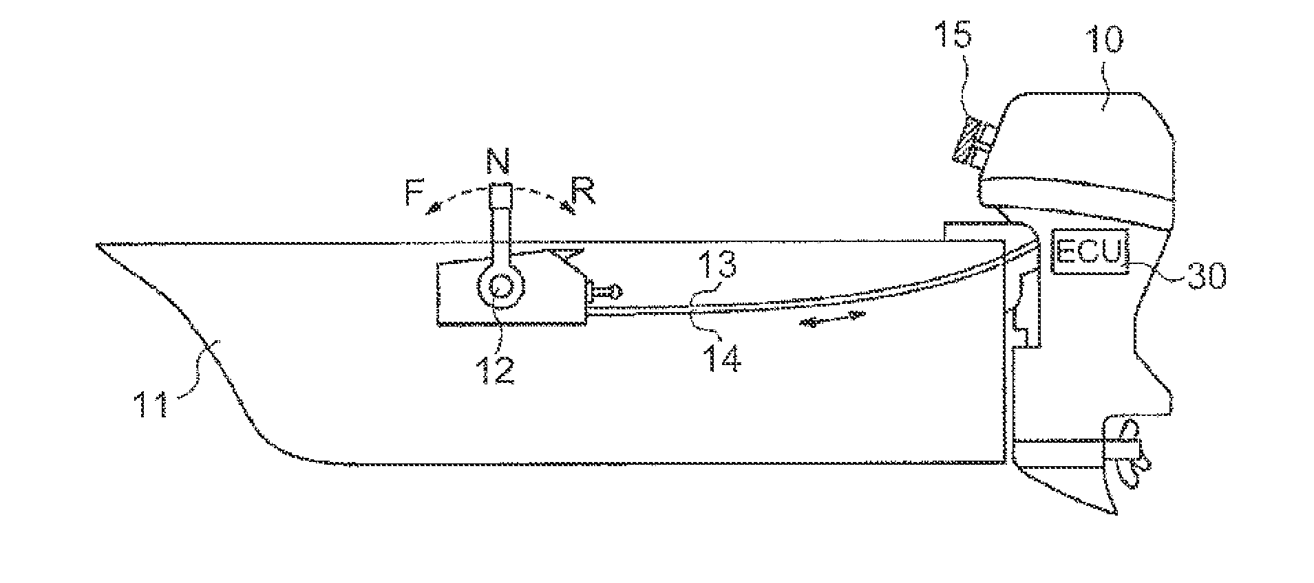
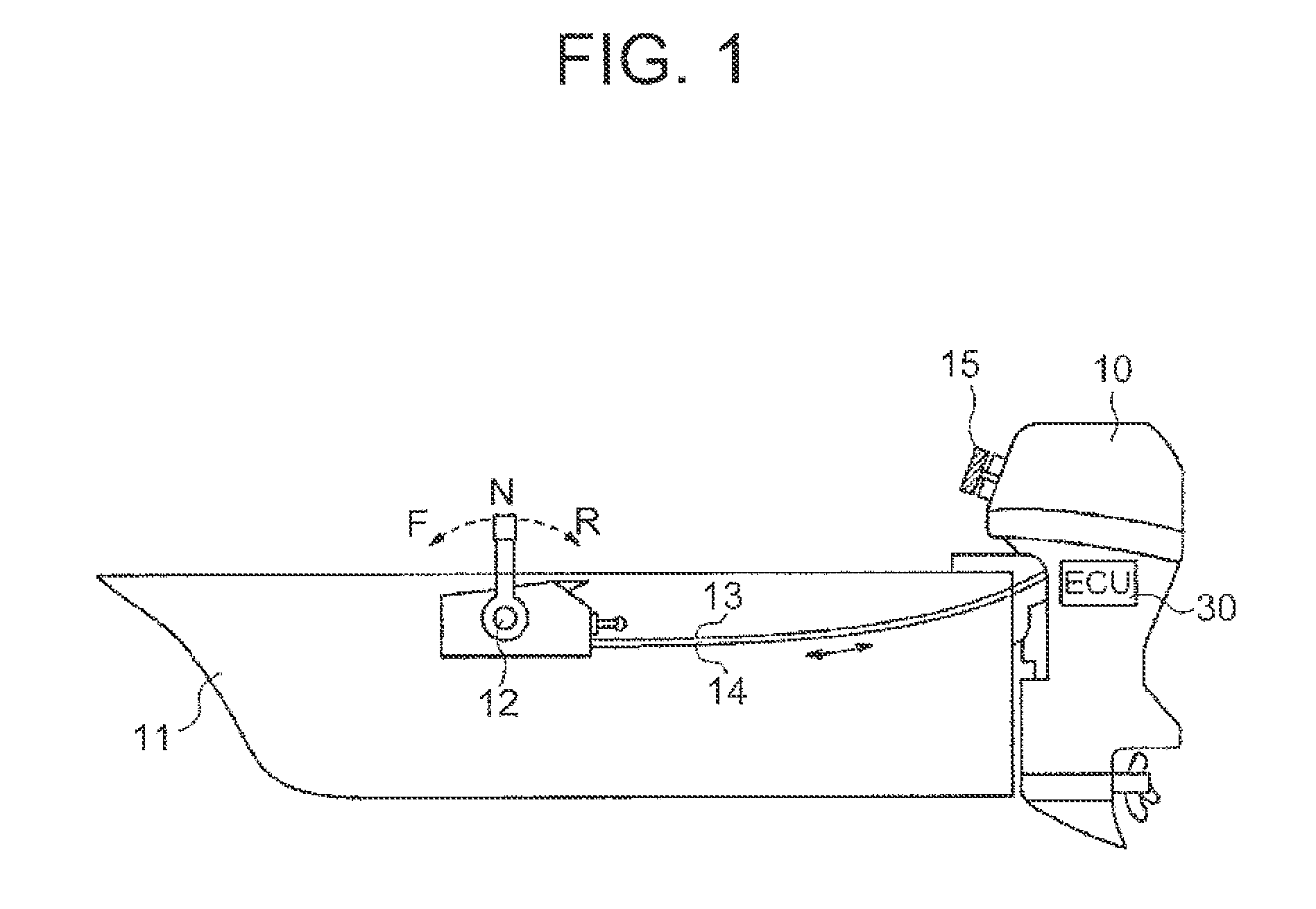
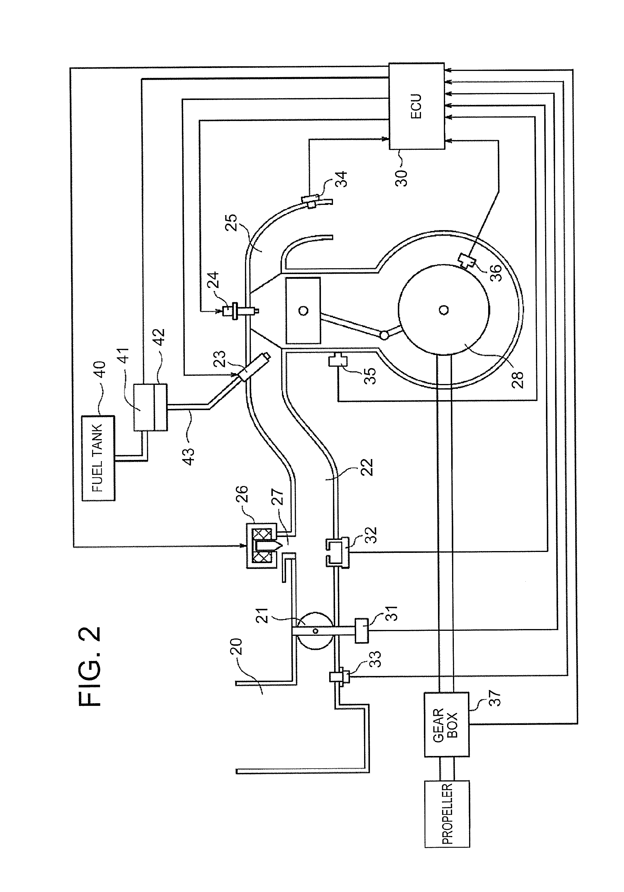
  • Boat engine idling revolution number control device and method
  • Boat engine idling revolution number control device and method
  • Boat engine idling revolution number control device and method

Examples


first embodiment

[0039]Prior to specific description of the present invention, contents of control to be executed by the boat engine idling revolution number control device according to the present invention are first outlined. In the present invention, conformed data is set for a rate of a torque which is desired to be generated to an engine torque necessary to maintain an engine revolution number at a target revolution number, specifically, a maximum torque which can be generated by the engine (the rate is referred to as “torque rate” in the following description) so that control is performed.

[0040]The torque rate which is necessary for the engine to be steadily operated at a predetermined revolution number when a shift position state is neutral varies depending on an engine friction. The engine friction is determined by an engine temperature and an engine revolution number for a steady operation. Therefore, map data containing the target revolution number and the engine temperature as parameters ...


PUM


Abstract

Provided is a boat engine idling revolution number control device, which includes a control unit (30) for performing control so that an engine revolution number converges to a target revolution number based on a result of detection of an engine state. The control unit includes: a decelerating running determining section (314); and a running-load correction calculating function section (315) for calculating a running-load correction signal for correcting a basic torque rate based on the result of determination by the decelerating running determining section and a shift position state detected by the neutral switch. The running-load correction calculating function section resets the running-load correction signal to zero when detecting, based on a behavior of the engine revolution number after the running-load correction, that the engine revolution number is larger than a threshold value calculated based on the target revolution number and the engine revolution number increases.

Description

BACKGROUND OF THE INVENTION[0001]1. Field of the Invention[0002]The present invention relates to a boat engine idling revolution number control device and method for appropriately controlling an engine idling revolution number of an internal combustion engine to be mounted on a boat.[0003]2. Description of the Related Art[0004]In the field of electronically-controlled internal combustion engines, the following technology of controlling an engine idling revolution number is conventionally well known. Specifically, when a predetermined idling condition is satisfied, an air amount to be supplied to the internal combustion engine (hereinafter also referred to as “engine”) is controlled so as to control an engine revolution number to a predetermined value. According to this kind of technology, the air amount is controlled by an air intake regulator valve in accordance with a difference between a target revolution number and an actual revolution number during the idling operation so that ...

Claims


Application Information

Patent Timeline
IPC IPC(8): F02D29/02F02D31/00
CPCF02D29/02F02D31/001F02D41/0225F02D41/16F02D41/2422F02D41/2448F02D41/2451F02P5/1508F02D31/005F02D41/0002F02D2041/1432F02D2200/021F02D2200/0411F02D2200/501F02D2200/502F02D2250/18Y02T10/40
Inventor YAMAGUCHI, YOHEIISHIDA, YASUHIKO
Owner MITSUBISHI ELECTRIC CORP
Learn More