UV wastewater treatment device

a wastewater treatment device and uv technology, applied in water cleaning, liquid displacement, separation processes, etc., can solve the problems that the uv treatment system of wastewater from the septic tank system did not include any safety provisions, and achieve the effect of reducing the cost and complexity of the devi

Inactive Publication Date: 2006-07-27
MOODY KENNETH W +1
View PDF22 Cites 6 Cited by
  • Summary
  • Abstract
  • Description
  • Claims
  • Application Information

AI Technical Summary

Benefits of technology

[0012] However, the specific objects of providing a device for UV treatment of wastewater which minimizes the cost and complexity of the device, provides safety elements to protect maintainers and enables remote monitoring of effectiveness of the UV treatment and remote control of the operation of the device have not been satisfied until the present invention. This is an apparatus for UV wastewater purification in septic tank systems, comprised of an Ultraviolet light bulb of approximate 30 inch length, encased in a clear crystal protective tube fitted with a protective cap at the bottom end and fixedly attached to a UV socket and suspended from a UV socket port in a top insert in the vertical treatment chamber, which vertical treatment chamber is limited by a bottom insert with ports therein through which wastewater flows into the vertical treatment chamber, around the UV protective tube up to no more than one inch above the bottom of the outflow pipe, determined by its location at the level of the septic tank outflow pipe, and then passes along the outflow pipe, being irradiated from above by the UV light, into the drain field. The portion of the UV light held above the top insert by a UV light retainer impinging in the UV socket port is removably encased in an UV shield having a photocell port there through, through which is removably retained the threaded end of the photocell to sense when the UV light is illuminated, which photocell is electrically connected at the unified plug, to which is also connected the main electrical lead to the UV socket, to the watertight electrical connection through the cap of the 30 inch long 6 inch diameter PVC straight pipe which extends above ground level, and extends to a remote monitor and control box containing a ballast having 120 volt 60 Hz input.
[0013] There are certain principals of effective treatment of wastewater with UV radiation which must be satisfied to maximize the treatment process while minimizing the cost thereof. First, the maximum effective treatment range of a UV light is 3 inches so the tube in which the UV light is located should be no larger than 4 inches in diameter. Second, the UV radiation effectiveness is increased where there is air between the light and the flow of the wastewater, provided the waste water is no deeper than one inch. Third, remote monitoring and control can be accomplished up to 40 feet when 18 gauge wire is used combined with an electronic ballast having an input of 120 volts and 60 Hz and the UV system is operated on low voltage which can be mated with a visual and audible alarm to indicate non-operation of the UV light and automatically turn off the system pump.

Problems solved by technology

It is well known that exposure of the human eye to UV rays can result in blindness.
Previous systems for UV treatment of wastewater from septic tank systems did not incorporate any safety provision for those who were required to access the system to clean and / or repair components.

Method used


Image

  • UV wastewater treatment device
  • UV wastewater treatment device
  • UV wastewater treatment device

Examples


Embodiment Construction

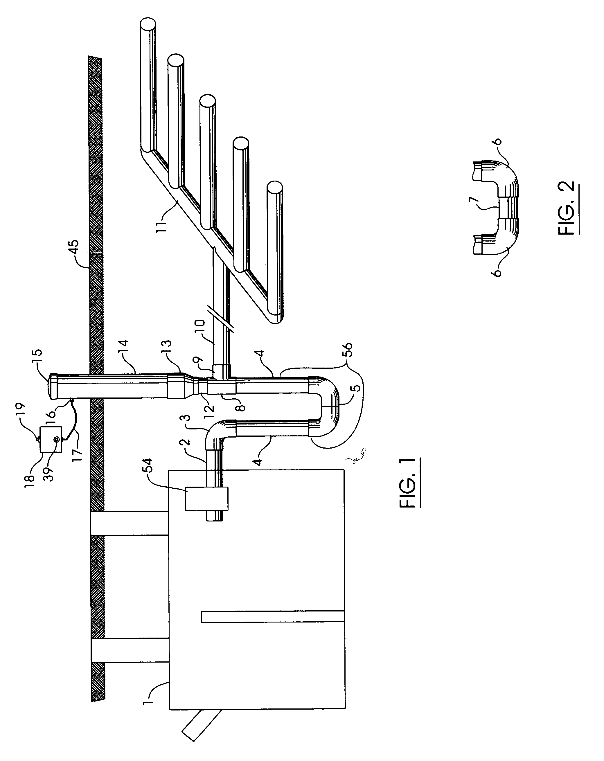
[0024]FIG. 1 shows a preferred embodiment of the invention installed between a septic tank (1), having a system pump (54), and the outflow pipe (10) to its drain field (11) beneath ground level (45) with only a portion of the 30 inch long 6 inch diameter PVC straight pipe (14) and the 6 inch PVC cap (15), from which runs an electrical wire (17) to a remote control box (18) with an alarm light (19) on top of box, extending above ground level (45).

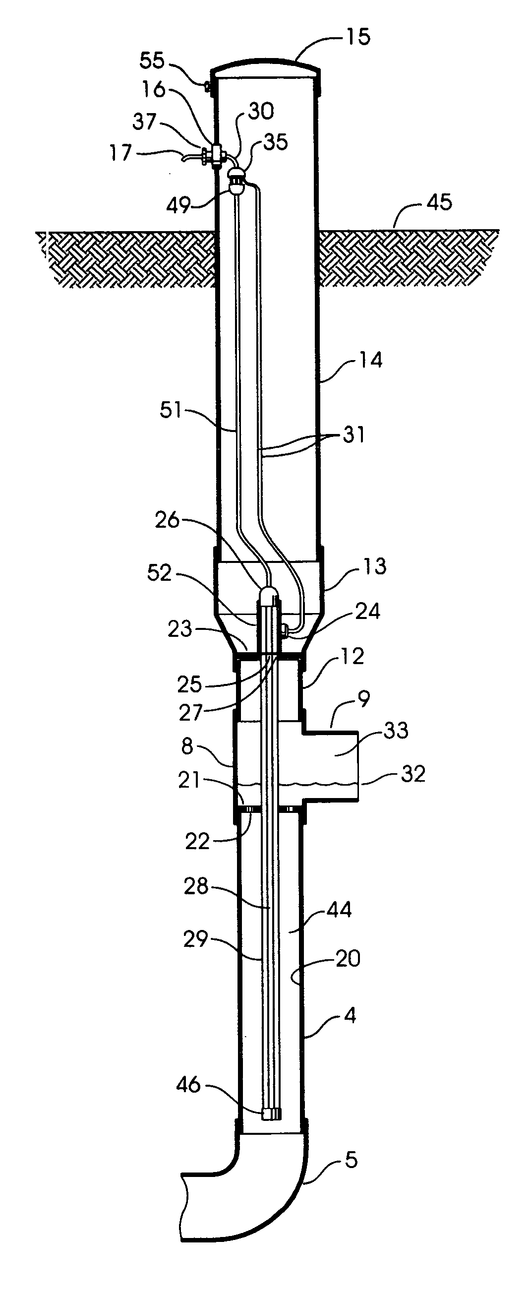
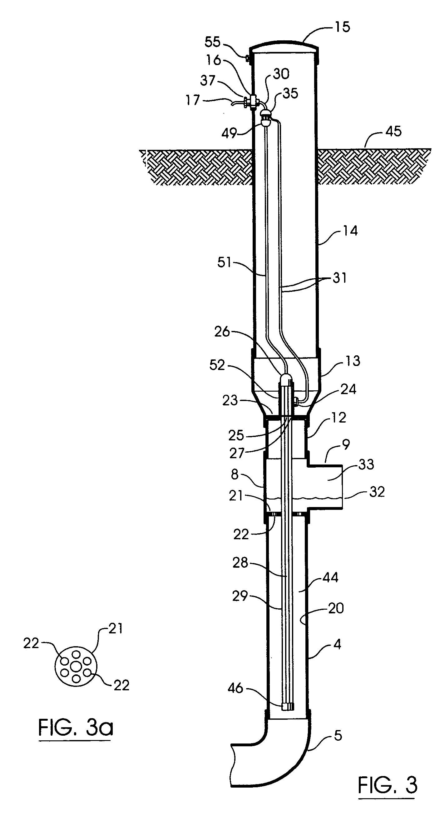
[0025] With specific reference to FIG. 2 and 3, the details of the preferred embodiment are shown. The improved apparatus for UV wastewater purification is installed between the septic tank (1) and the drain field (11) at such a depth below ground level (45) so that the elbow (3) communicates with the septic tank outflow pipe (2) resulting in the maximum level of the outflow water level (32) being no more than one inch above the bottom of the outflow arm (9) of the PVC ‘T’ fitting (8).

[0026] With specific reference to FIG. 3, the preferred...


PUM

PropertyMeasurementUnit
Lengthaaaaaaaaaa
Lengthaaaaaaaaaa
Lengthaaaaaaaaaa

Abstract

An improved apparatus for UV wastewater purification in septic tank systems disposed in piping located between tank and drainfield and method for use, comprised of an inlet end, removable for cleaning, a descending section, a connecting section, a vertical section, with outflow tube, and containing a UV light, having provision for preventing removal when illuminated, with protective tube spanning its vertical length, with a built-in bottom insert with ports therein to restrict passage of solids and a built-in top insert with a port therein to hold the UV socket and photocell which communicates to a remote control panel.

Description

CROSS-REFERENCE TO RELATED APPLICATIONS [0001] U.S. Pat. No. 6,296,775 B1 issued Oct. 2, 2001STATEMENT REGARDING FEDERALLY SPONSORED RESEARCH OR DEVELOPMENT [0002] NONE [0003] Reference to a “Sequence Listing,” a table, or a computer program listing appendix submitted on a compact disc (see 37 CFR 1.52(e)(5)): NONE BACKGROUND OF THE INVENTION [0004] (1) Field of the Invention [0005] This invention relates generally to UV treatment of waste water from septic tank systems and more particularly to an improved means maximizing the effectiveness of the UV light, establishing safety protection for maintainers, and provision of remote control and monitoring the effectiveness of the process and method therefore. [0006] (2) Description of Related Art including Information Disclosed under 37 CFR 1.97 and 1.98 [0007] It has been long established that wastewater from septic systems needed to be purified before passing it to the drain field. Originally, the effluent was treated by exposure to th...

Claims


Application Information

Patent Timeline
IPC IPC(8): C02F1/32
CPCC02F1/325C02F2201/3223C02F2201/3228C02F2201/326
Inventor MOODY, KENNETH W.DALLY, JANET L.
Owner MOODY KENNETH W
Why Eureka
Try Eureka