
Heat exchanger

a technology of heat exchanger and header tank, which is applied in the direction of filtration separation, lighting and heating apparatus, and separation processes, etc., can solve the problems of increasing the volume of the header tank, deteriorating productivity, and complicated structure of the heat exchanger, so as to improve productivity, pressure resistance and durability, and easy to change the flow channel of the refrigerant.

Inactive Publication Date: 2006-07-27
HANON SYST
View PDF8 Cites 54 Cited by
  • Summary
  • Abstract
  • Description
  • Claims
  • Application Information

AI Technical Summary

Benefits of technology

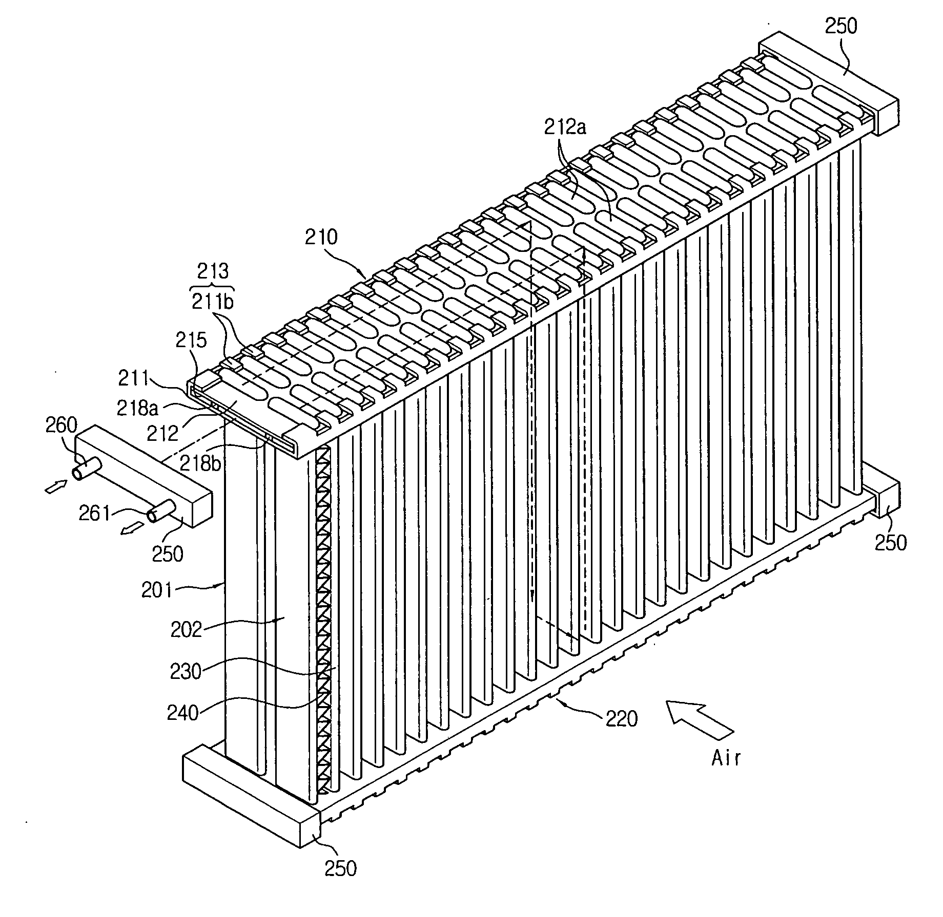
[0014] Accordingly, it is an object of the present invention to provide a heat exchanger, in which a tank having a number of domes is coupled with a header and a connection member having a connection flow channel is interposed between the header and the tank, thereby easily changing a refrigerant flow channel, reducing the volume of a header tank, and improving productivity, pressure resistance and durability.

Problems solved by technology

However, such prior art heat exchangers are complicated in structure and deteriorated in productivity, or increase the volume of the header tank since it has the structure for surrounding the outer surface with the brazing material.

Method used

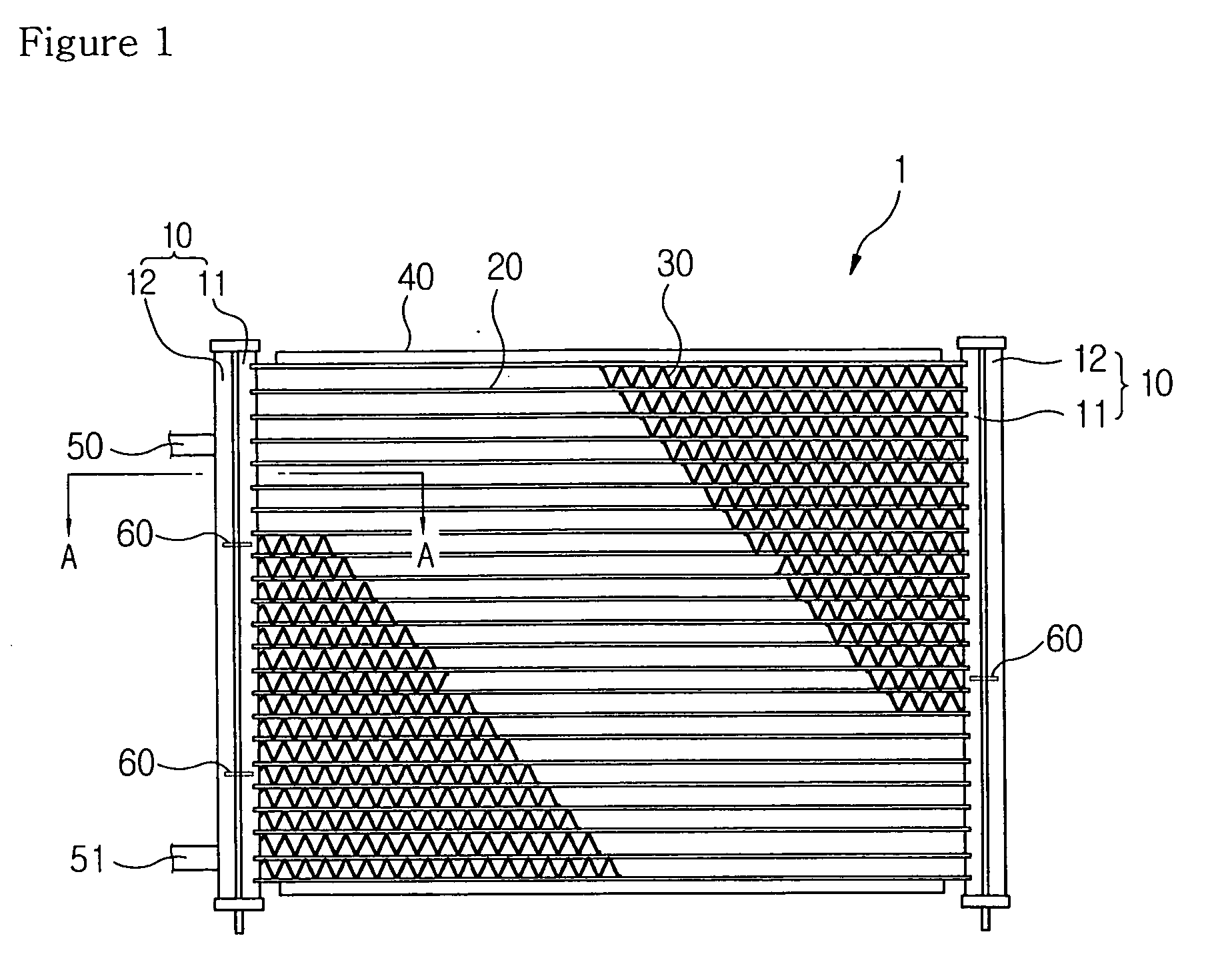
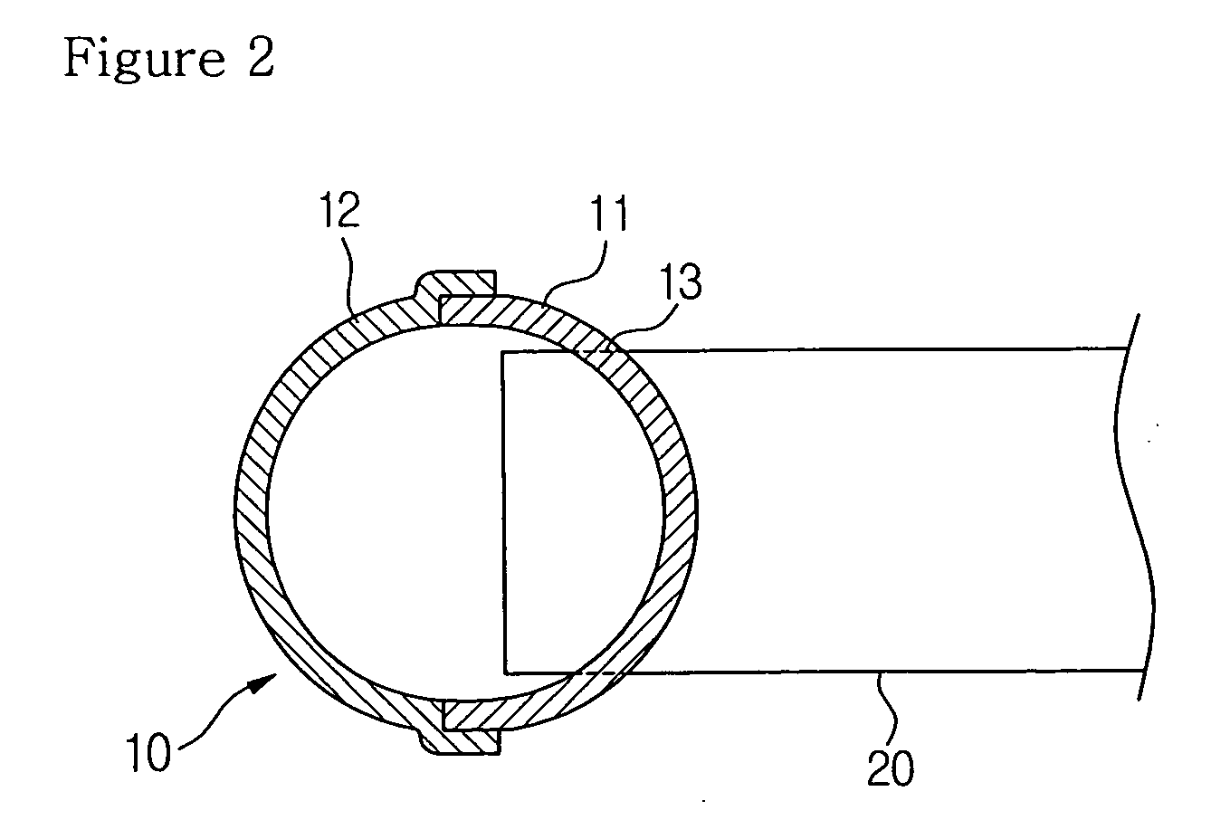

Image

  • Heat exchanger
  • Heat exchanger
  • Heat exchanger

Examples


Embodiment Construction

[0029] Reference will now be made in detail to the preferred embodiments of the present invention, examples of which are illustrated in the accompanying drawings.

[0030] Description of the same constitution and operation as the prior arts will be omitted.

[0031]FIG. 3 is a perspective view of a heat exchanger according to a first preferred embodiment of the present invention, FIG. 4 is an exploded perspective view of the heat exchanger according to the first preferred embodiment of the present invention, FIG. 5 is a sectional view taken along a line of B-B in FIG. 3, FIG. 6 is a perspective view showing a state where baffles are formed on a connection member in the heat exchanger according to the first preferred embodiment of the present invention, FIG. 7 is a sectional view showing a state where two connection members are vertically laminated in the heat exchanger according to the first preferred embodiment of the present invention, and FIG. 8 is a sectional view showing another ex...


PUM

PropertyMeasurementUnit
Lengthaaaaaaaaaa
Electrical resistanceaaaaaaaaaa
Sizeaaaaaaaaaa

Abstract

The present invention relates to a heat exchanger for carbon dioxide, in which a tank having a number of domes is coupled with a header and a connection member having a connection flow channel is interposed between the header and the tank, thereby easily changing a refrigerant flow channel, reducing the volume of a header tank, and improving productivity, pressure resistance and durability.

Description

BACKGROUND OF THE INVENTION [0001] 1. Field of the Invention [0002] The present invention relates to a heat exchanger, and more particularly, to a heat exchanger for carbon dioxide, in which a tank having a number of domes is coupled with a header and a connection member having a connection flow channel is interposed between the header and the tank, thereby easily changing a refrigerant flow channel, reducing the volume of a header tank, and improving productivity, pressure resistance and durability. [0003] 2. Background Art [0004] In general, a heat exchanger is installed on a flow channel of a cooling system or a heating system for cooling or heating a predetermined space by exchanging heat in such a way that heat exchange medium flowing inside the passageway sucks the outside heat or radiates its heat to the outside. [0005] Such heat exchanger is classified into a condenser and an evaporator using refrigerant as heat exchange medium and a radiator and a heater core using cooling ...

Claims


Application Information

Patent Timeline
IPC IPC(8): F28F9/02F28D7/06F25B39/04
CPCF25B39/00F25B2309/061F28F9/0221F28F9/0224F28F9/0278B01D35/147
Inventor PARK, TAEYOUNGOH, KWANGHEONLEE, DUCKHO
Owner HANON SYST
Learn More