
A Shape Memory Alloy MEMS Heat Engine

a heat engine and shape memory technology, applied in the direction of machines/engines, non-positive displacement fluid engines, hot gas positive engine plants, etc., can solve the problems of inability to achieve practical engineering applications, the theoretical upper limit of efficiency (carnot efficiency) approaching only 4-5%, and the design of most heat engine designs are extremely complex. , to achieve the effect of reducing friction forces, increasing the possible operation frequency of sma-mems heat engine, and easy scaling of the design devi

Inactive Publication Date: 2006-07-27
KIRKPATIRCK SCOTT RYAN +3
View PDF22 Cites 29 Cited by
  • Summary
  • Abstract
  • Description
  • Claims
  • Application Information

AI Technical Summary

Benefits of technology

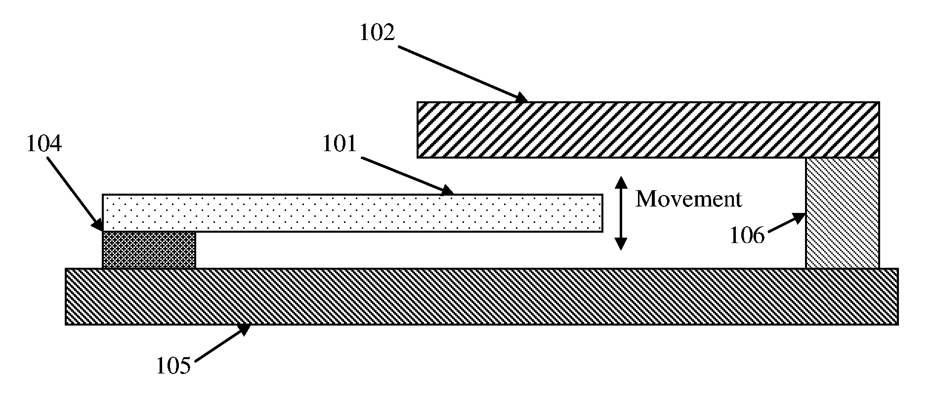
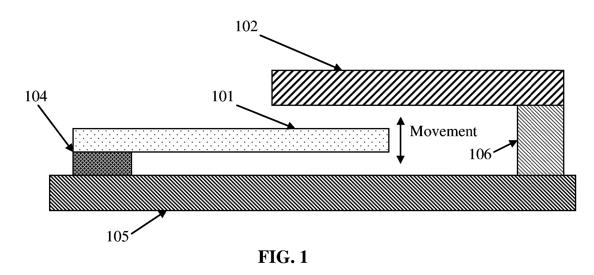
[0009] The SMA-MEMS heat engine provides solutions to problems associated with other micro-engines that utilize different modus operandi, as well as problems encountered in macro-sized SMA engines, and thereby provides unexpected beneficial and synergistic results. The present invention solves these problems by taking advantage of design concepts suited for microapplications. Specifically, smaller objects cool faster, increasing the possible operation frequency of an SMA-MEMS heat engine over macro-sized engines. Furthermore, the microscale electrostatic forces and electromagnetic forces also become much more significant thus providing excellent mechanisms for power conversion. The oscillating beam design described here has no rubbing parts thus reducing friction forces compared to typical engine designs. The design also takes advantage of the mass production capabilities of silicon batch processing. This allows easy scaling of the designed device by simply increasing the number of heat engines attached to any temperature gradient or hot and cold sources. OBJECT OF THE INVENTION

Problems solved by technology

However, practical engineering applications were not successful, as the theoretical upper limit of efficiency (Carnot efficiency) approached only 4-5%.
Furthermore, most heat engine designs were extremely complex.
This is likely due to the extremely complicated designs required by prior SMA heat engines used as visual demonstrations.
Such favorable scalings provide for fast heat transfer rates and large temperature gradients for an SMA-MEMS heat engine, features which are absent in macro-sized SMA heat engines and therefore significantly hinder their performance and efficiency.
In summary, the prior art MEMS engines suffer from large losses through friction and other losses to the point where they nearly have difficulty producing more energy than they require to operate.
SMA-macro engines lack sufficient thermal gradients, speed, efficiency and adequate harnessing mechanisms for operation.

Method used


Image

  • A Shape Memory Alloy MEMS Heat Engine
  • A Shape Memory Alloy MEMS Heat Engine
  • A Shape Memory Alloy MEMS Heat Engine

Examples


second embodiment

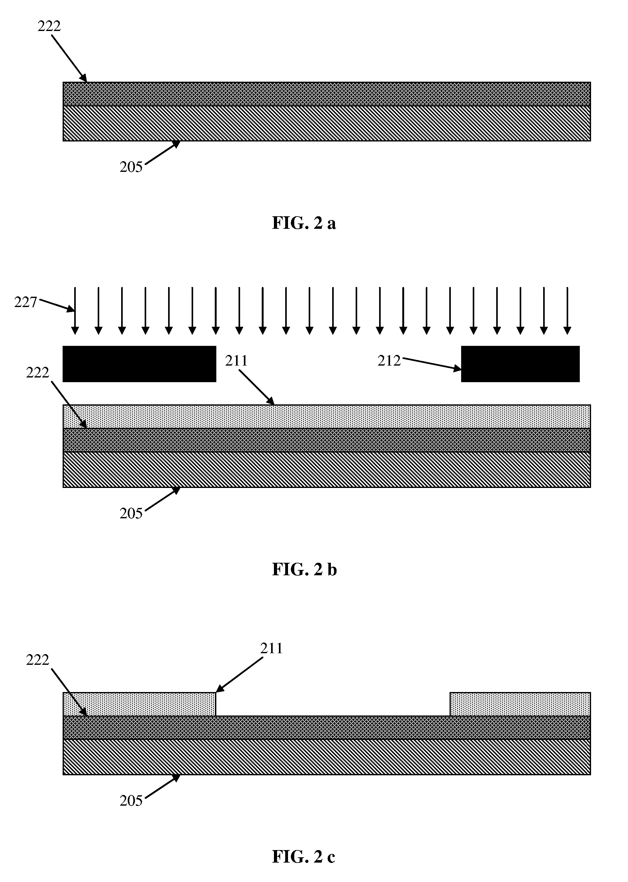
[0026] Standard MEMS fabrication procedures known to one of ordinary skill in the art may be employed for creating the TiNi thin film heat engines. Specifics of the steps in the fabrication procedures are given below, which is the second embodiment as a vertical lifting mechanism.

[0027] Prior to deposition of the TiNi layer, an oxide layer 222 is deposited using e-beam evaporation on a silicon wafer 205 or other suitable substrate, followed by photoresist 211. The photoresist is then exposed to radiation 227 typically ultraviolet light and developed. The photoresist pattern 212 consists of windows ranging from several microns to 1 mm in width and tens of microns to 1 mm in length.

[0028] The TiNi or other suitable shape memory alloy thin film is then deposited 221 on the silicon dioxide layer at an elevated temperature. The TiNi thin film can be deposited using either a sputtering procedure, or with a co-evaporation procedure in which titanium and nickel are deposited using e-beam a...

third embodiment

[0030] In a third embodiment an applied load from a spring is set to allow the engine to operate. This design is shown in FIG. 4 and FIG. 5. In FIG. 4 the load “q” applied to the cantilever tip allows the displacement “v” of the beam when supplied with a hot and cold source (in this case the anchor). As shown in FIG. 5, this second design harnesses the stress strain relationship of the shape memory alloy by the attached spring 515 at the end of the cantilever beam 501, and a “zip-strip” type mechanism 516 and 527 for mechanically applying a force to the cantilever beam. The “zip strip” mechanism allows a stress to be applied to the cantilever beam 501 after processing. A secondary MEMS device or probe moves the ring 517 which moves the serrations 516. The serrations 516 move past a set of herring bone beams 527 allowing motion in only one direction. This results in a stress being applied to the beam 501. Spring 515 may be added to add greater flexibility in the force applied to the ...


PUM

PropertyMeasurementUnit
temperatureaaaaaaaaaa
thicknessaaaaaaaaaa
thickaaaaaaaaaa

Abstract

A microelectromechanical systems (MEMS) based heat engine capable of converting thermal energy gradients into mechanical or electrical energy, as well as its fabrication process is disclosed. This heat engine design consists of a stressed oscillating beam formed from a shape memory alloy (SMA) thin film. As the temperature of the beam changes, its shape changes due to the phase transformation of the shape memory alloy, causing it to oscillate between a hot source and a cold source. Due to the hysteretic behavior of the phase transformation, the oscillating SMA cantilever beam produces a net mechanical work output that may be either converted to electrical energy or mechanically linked to other MEMS devices.

Description

BACKGROUND OF THE INVENTION [0001] The first known observation of the shape memory transformation was by Chang and Read in 1932. They noted the reversibility of the α solid phase transformation in a gold cadmium (AuCd) alloy from metallographic observations and resistivity change measurements. In 1951 the shape memory effect (SME) itself was observed in a bent bar of AuCd. Then in 1962 Buehler et al. discovered the SME effect in nickel-titanium (NiTi). The group named the alloy “Nitinol”, after its elemental components and place of origin. The “Ni” and “Ti” are the atomic symbols for nickel and titanium, respectively, the “NOL” stands for the Naval Ordinance Laboratory. [0002] The first use of an SMA in a heat engine application, in which thermal energy is changed into mechanical work, was accomplished in 1973 by Ridgway Banks and Hap Hagopian of the Lawrence Berkely Laboratory at the University of California. SMA heat engines became very popular as fascinating visual demonstrations...

Claims


Application Information

Patent Timeline
Patent Type & Authority Applications(United States)
IPC IPC(8): F01B29/10F02G1/04
CPCF03G7/065F04D33/00
Inventor KIRKPATIRCK, SCOTT RYANSIAHMAKOUN, AZADADAMS, THOMAS MCDANIELWANG, ZHEFU
Owner KIRKPATIRCK SCOTT RYAN
Learn More