
Method for releasably connecting two groups of optical fibers, and plug-in connector for carrying out said method

Inactive Publication Date: 2006-07-20
HUBERSUHNER AG
View PDF8 Cites 12 Cited by
  • Summary
  • Abstract
  • Description
  • Claims
  • Application Information

AI Technical Summary

Benefits of technology

[0012] The object of the invention is to provide a method for releasably connecting two groups of optical fibers which avoids the disadvantages of known solutions, in particular the disadvantages accompanying the “buckling” or bending of the fibers, and at the same time, makes precisely aligned and optically high-quality contact of all the pairs of fibers possible, and also provides a plug-in connector for carrying out the method that can be inexpensively produced.
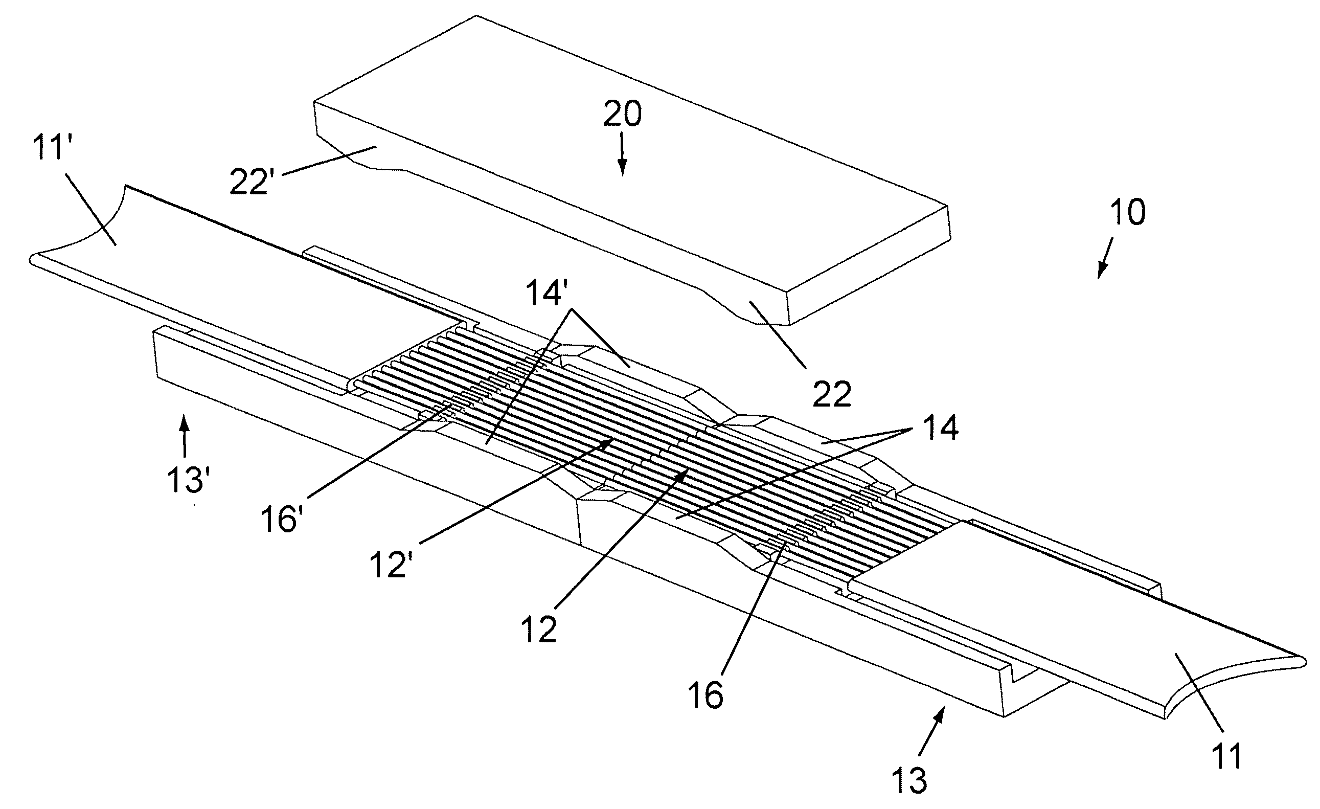
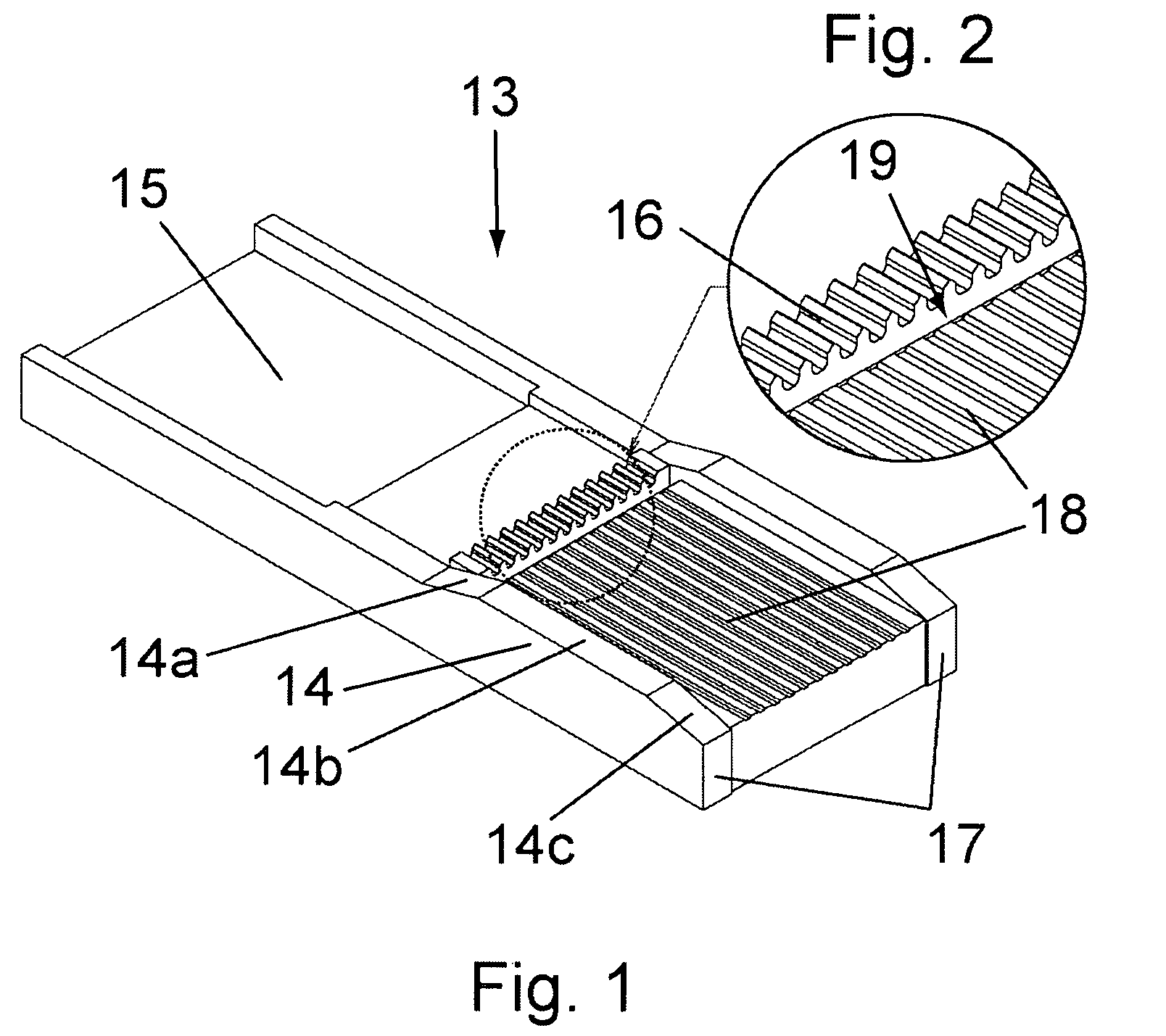
[0014] According to a preferred embodiment of the method of the present invention, the individual fibers of the two groups are movably supported over a predetermined free length, and the fibers are fixed in the lateral direction over the predominant part of their free length during alignment. The lateral fixing effectively makes virtually the entire free length of the fibers available for the elastic compression, so that the compressive stress accompanying a fiber length variation tolerance compensation is homogeneously distributed over the free length of the fibers, and consequently the elastic deformations are kept small.
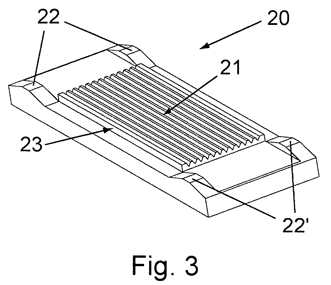
[0018] Another preferred embodiment of the present invention is distinguished by the fact that the aligning element for aligning and fixing the fibers is lowered onto the fiber blocks in a relative movement that is transverse in relation to the fiber's axial direction until the fibers lie in pairs in the associated guiding profile and are laterally fixed. The movement of the aligning element in relation to the fiber blocks takes place coupled with the relative movement of the fiber blocks in relation to one another, and the coupling of the movements of the fiber blocks and of the aligning element takes place by means of lateral guiding geometries on the fiber blocks and side guides acting with them on the aligning element. As a result, simple and reliable alignment and fixing of the pairs of fibers can be achieved. It goes without saying that the means for coupling the movements of the fiber blocks and of the aligning element may also be differently configured and placed at different locations of the plug-in connection within the scope of the invention.
[0019] It is particularly advantageous if the guiding profiles in the aligning element become narrower with increasing depth vertically in relation to the guiding direction, in particular are formed in a V-shaped manner, and if, during the alignment and fixing, the pairs of fibers are pressed into the guiding profiles by elastically deformable means attached to the fiber blocks.
[0025] The fiber blocks preferably consist of a dimensionally stable material that is adapted to the fibers in the coefficient of thermal expansion, in particular, a ceramic material. In addition, the fiber blocks may be polished on the end faces. In contrast, the aligning element is preferably produced from a plastic material, and, more specifically, by an injection-molding process. To increase the surface hardness of the associated guiding profiles and to reduce the sliding friction of the fibers on the surface, it may be coated with a dielectric or metallic material or a combination of materials.

Problems solved by technology

However, the potential for further miniaturization and for lowering the production costs is limited.
However, the construction of these multiple plug-in connectors with single ferrules is complicated and elaborate and leads to comparatively high plug-in forces.
In the case of the connectors based on MT ferrules (see, for example, FIG. 7 of the initially cited US-B2-6,582,134), the high packing density is obtained, but the performance and reliability are usually only adequately ensured in multimode operation (MM).
Although single-mode variants (SM) are available, they impose very high requirements on the production technologies and are consequently relatively expensive to produce.
Moreover, the high precision in the positioning of the fibers that can be achieved with the molded (usually injection-molded) parts of the MT ferrules is partly undermined by the cummulative tolerances over the guiding pins, which are made with relatively great dimensions in relation to the fibers.
The ferrule, which is usually produced from thermoplastic and in which these pins are embedded, is subjected to high mechanical loads when it undergoes repeated plugging and unplugging and temperature fluctuations.
This and the fact that individual dirt particles can endanger the functional capability of a number of fiber connections based on the large contact area, represents a significant risk to reliability.
However, the relatively strong deformation of the fibers also entails decisive disadvantages: on the one hand, the buckling does not go below a minimum bending radius, in order to avoid additional optical losses (specifically polarization-dependent losses).
As a result, the minimum overall length of the plug-in connectors is limited.
On the other hand, the risk of fiber rupture is increased by the flexural stresses, as a consequence of which the reliability may be impaired.
Finally, the radially non-symmetric stresses occurring during the buckling of the fibers may lead to permanent changes in the optical transmission behavior.
Although allowance are made for these problems by using special fibers with greater bending resistance or specially coated glass fibers, such additional measures increase the production costs and make acceptance by users more difficult.

Method used


Image

  • Method for releasably connecting two groups of optical fibers, and plug-in connector for carrying out said method
  • Method for releasably connecting two groups of optical fibers, and plug-in connector for carrying out said method
  • Method for releasably connecting two groups of optical fibers, and plug-in connector for carrying out said method

Examples


Embodiment Construction

[0037] The present invention is designed in such a way that it meets the following requirements without a ferrule: [0038] suitable for monomode and multimode [0039] low insertion loss [0040] temperature range: −40° . . . 85° C. [0041] high plugging reliability [0042] high mechanical stability [0043] connection of multifiber cables (with preferably 8 or 12 single fibers) or any number of single fibers [0044] plug-in connector for any contact spacing and diameter of the fibers (preferably fibers with a diameter of 125 micrometers and equidistant spacing of 250 micrometers)

[0045] The basic physical necessities for efficient optical coupling between two fibers in physical contact (PC) comprise adequately good mutual lateral centering, best possible surface quality of the fiber end face and a minimal axial pressing force of the order of magnitude of about 0.4 N per fiber (see for example the article by M. Kobayashi et al., Injection Molded Plastic Multifiber Connector Realizing Physical...


PUM


Abstract

Disclosed is a method for removably connecting two groups of individual, parallel fibers that are delimited by end faces that are perpendicular to the fiber axis. The two groups of fibers are moved towards each other in an axial direction until each of the fibers abuts against the end face of the assigned fiber from the other group. The fibers of the two groups are aligned in pairs relative to each other before being moved into contact with each other, and any differences in fiber lengths is compensated for by elastically deforming the fiber along the fiber main axis. This method eliminates the disadvantages associated with bending the fibers because length variations are essentially compensated for by axially compressing the fibers.

Description

CROSS REFERENCE TO RELATED APPLICATION [0001] This application is a continuation of International Application No. PCT / CH2004 / 000347 having an international filing date of Jun. 8, 2004, and which designated the United States, the entirety of which is incorporated herein by reference.FIELD OF THE INVENTION [0002] The present invention relates to the field of information transmission by means of optical fibers. It concerns a method for releasably connecting two groups of optical fibers arranged in parallel and delimited by end faces that end in a plane transverse to the fiber main axis, and a plug-in connector for carrying out the method. Such a method is known for example from the document US-B2-6,582,134. BACKGROUND OF THE INVENTION [0003] In the art of optical information transmission by means of glass fiber cables, for reasons of increasing integration there is the desire for a ferrule-less fiber optical plug-in connector of high packing density. The applications of such a connecto...

Claims


Application Information

Patent Timeline
IPC IPC(8): G02B6/38
CPCG02B6/3636G02B6/3652G02B6/3692G02B6/3696G02B6/3809G02B6/3821G02B6/3885
Inventor AMMER, THOMASGOEBEL, UHLANDSTRASSER, MARTINDRAHEIM, FALKNUECHTER, PETERCOMPARE, CARLO
Owner HUBERSUHNER AG
Learn More