Mobile device, system and method for enhanced channel allocation when radio resource connection is released while in dual transfer mode

Inactive Publication Date: 2006-07-20
CORE WIRELESS LICENSING R L
View PDF8 Cites 17 Cited by
  • Summary
  • Abstract
  • Description
  • Claims
  • Application Information

AI Technical Summary

Benefits of technology

[0011] The present invention describes how radio resources used for an RR connection can be converted to packet resources without any additional signaling in the radio interface, and how the network can indicate allocated radio resources to be used in packet transfer mode by the MS after the release of an RR connection while in dual transfer mode. This invention improves upon the prior art, so that packet resources can be allocated in a flexible manner when the RR connection is released while in dual transfer mode.
[0012] According to the present invention, unnecessary additional signaling, such as transmission of a PACKET TIMESLOT RECONFIGURE message, in packet transfer mode can be avoided, because channel allocation is already transmitted while in dual transfer mode. Moreover, the network may allocate more radio resources, which the mobile device can use immediately after the release of the RR connection.

Problems solved by technology

When the use of GSM data services began, it became evident that the Circuit Switched (CS) bearer services were not particularly well-suited for certain types of applications with a bursty nature.
A problem occurs with MS behavior when the MS operates in the class A mode (i.e. dual transfer mode) of operation.
Unfortunately, the present standard does not specify the allocation of timeslots (i.e. the number and location in the TDMA structure is not specified) to be used in packet transfer mode after the release of the RR connection.
However, there is currently no way to flexibly allocate packet resources when the RR connection is released while in dual transfer mode.

Method used


Image

  • Mobile device, system and method for enhanced channel allocation when radio resource connection is released while in dual transfer mode
  • Mobile device, system and method for enhanced channel allocation when radio resource connection is released while in dual transfer mode
  • Mobile device, system and method for enhanced channel allocation when radio resource connection is released while in dual transfer mode

Examples


Embodiment Construction

[0022] Two primary embodiments will be described here: a conversion solution, and also a reconfiguration solution. However, it is to be understood that these embodiments are examples of how the present invention can be implemented, and are not to be construed as limiting the scope of the invention.

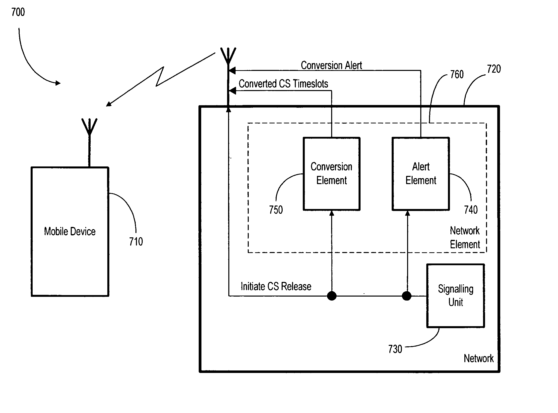
[0023] Regarding the conversion solution, a first option involves minimal change to the current working assumption, and would keep in packet transfer mode the same radio resources on one or more Packet Data Channels (PDCHs) than assigned in dual transfer mode. In addition, the network may make a conversion from the radio resources allocated for the RR connection to the packet resources. In dual transfer mode, the allocated radio resource for the RR connection can be either a full timeslot or half timeslot shared with packet transfer. In both cases, it is proposed that the network may make a conversion for the timeslot used for RR connection traffic (e.g traffic channels TCH / F or TCH / H) to...


PUM


Abstract

A mobile device, system, and method are disclosed for use in a wireless communication system during the mobile device's transition from a dual mode, in which a packet switched connection and circuit switched connection are used together, to a single mode in which packets are transferred. When the circuit switched connection is released, packet resources are allocated by converting timeslots used for circuit switched connection traffic into timeslots used for packet data traffic. Also included is a new alert signal within an existing message to the mobile device during the circuit switched connection release phase, before completion of the circuit switched connection release phase, in order to inform the mobile device that the converting step will occur after release of the circuit switched connection.

Description

CROSS REFERENCE TO RELATED APPLICATION [0001] The present invention claims priority to U.S. Provisional Patent Application 60 / 641,911 filed Jan. 5, 2005.FIELD OF THE INVENTION [0002] The present invention relates to wireless communication, and more particularly to packet switching and circuit switching for wirelessly communicating with a mobile terminal. BACKGROUND OF THE INVENTION [0003] The first GSM (Global System for Mobile communication) networks were designed for voice services. When the use of GSM data services began, it became evident that the Circuit Switched (CS) bearer services were not particularly well-suited for certain types of applications with a bursty nature. Therefore, the new Packet Switched (PS) data transmission service GPRS (General Packet Radio Service) was defined for packet services. GPRS is a packet radio network utilising the GSM network, which endeavours to optimize data packet transmission by means of GPRS protocol layers on the air interface between a ...

Claims


Application Information

Patent Timeline
IPC IPC(8): H04B7/212H04L12/43H04W72/04H04W76/04H04W76/06H04W88/06
CPCH04J3/1682H04W88/06H04W76/064H04W76/06H04W76/30H04W76/34H04W68/005H04W74/02H04W74/04H04W72/53H04W72/23
Inventor VAITTINEN, RAMIKANGAS, ANTTI O.
Owner CORE WIRELESS LICENSING R L
Why Eureka
Try Eureka