
Method and apparatus for diagnosing an abnormality of a gas-concentration measuring apparatus

a technology of gas concentration and measuring equipment, which is applied in the direction of electrical control, instruments, material electrochemical variables, etc., can solve the problems of not being able to know which of the cell electrodes is shorted, not being able to output, and incurring cost increases

Active Publication Date: 2006-07-20
NGK SPARK PLUG CO LTD
View PDF8 Cites 36 Cited by
  • Summary
  • Abstract
  • Description
  • Claims
  • Application Information

AI Technical Summary

Benefits of technology

[0014] Accordingly, in the case that an abnormality-diagnosing current is passed to the sensor device to thereby diagnosing an abnormality based on a voltage across the sensor device at that time for example, a potential difference is provided great across the sensor device because current supply is made in a high internal resistance state of the sensor device, thus enabling a positive abnormality diagnosis.
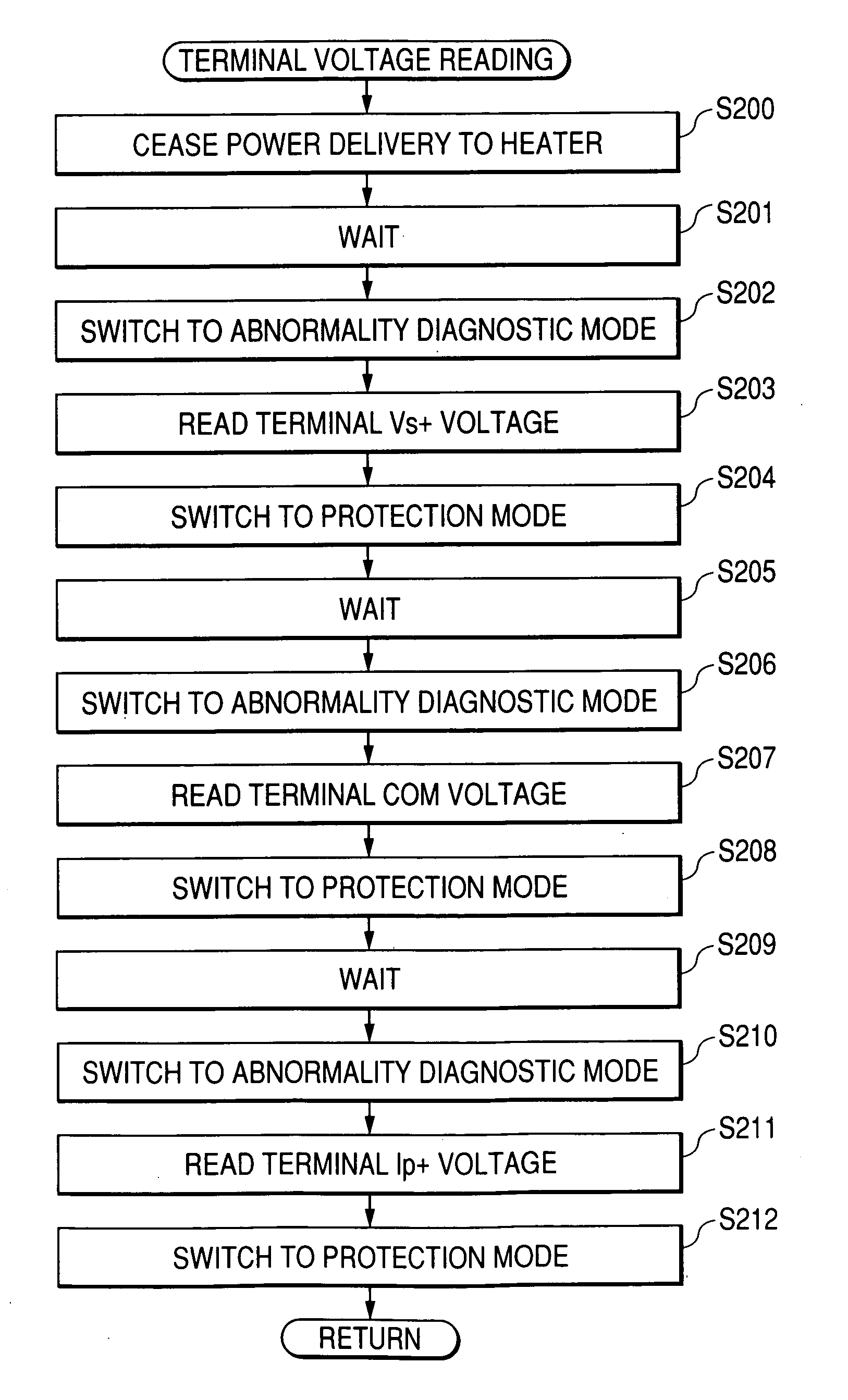
[0033] This can lower the temperature of the sensor device by the simple way of shutting off the delivery of power to the heating section.

Problems solved by technology

Thus, there is a problem that, where abnormality diagnosis is made based on the voltage across the cell at a relevant time by passing an abnormality-diagnosing current to the cell, there are possible cases a voltage, required for abnormality diagnosis, is not to be outputted onto the respective ends of the cell.
This results in a problem that it could not be known which one of the cell electrodes is shorted to GND.
This however necessitates a current source having a great capacity, which incurs cost increase.
Meanwhile, there is another problem that flowing a large current through the cell results in an accelerated deterioration of the cell.

Method used


Image

  • Method and apparatus for diagnosing an abnormality of a gas-concentration measuring apparatus
  • Method and apparatus for diagnosing an abnormality of a gas-concentration measuring apparatus
  • Method and apparatus for diagnosing an abnormality of a gas-concentration measuring apparatus

Examples


Embodiment Construction

[0040] Now, an embodiment of the present invention will be explained on the basis of the drawings.

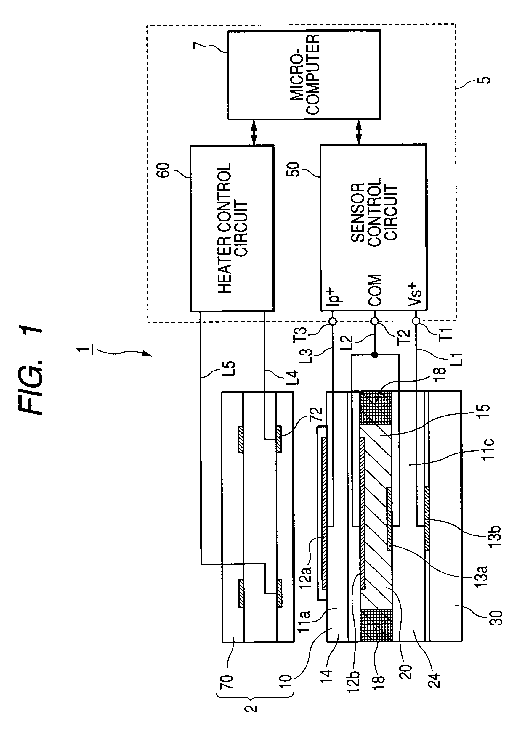
[0041]FIG. 1 is a schematic diagram showing a structure of a gas-concentration measuring apparatus 1 to which the invention is applied. The gas-concentration measuring apparatus 1 in this embodiment is for measuring a concentration of the oxygen contained in the exhaust gas of an internal combustion engine.

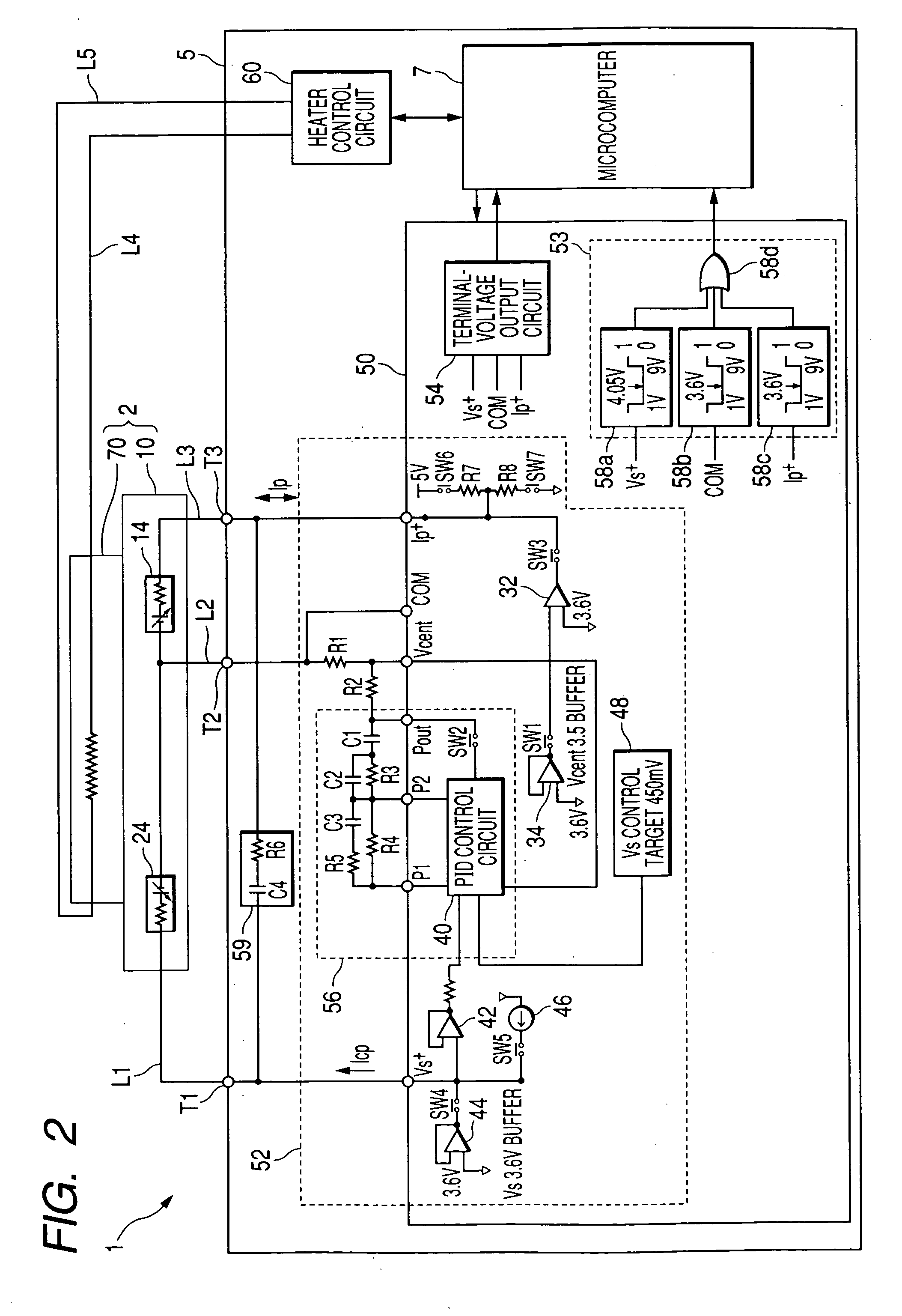
[0042] As shown in FIG. 1, the gas-concentration measuring apparatus 1 in this embodiment is constructed with a gas sensor 2, and an electronic control unit 5 (hereinafter, referred also as ECU 5) electrically connected to the gas sensor 2 and having a function to measure, or so, an oxygen concentration of a sample gas.

[0043] The gas sensor 2 includes a sensor device 10 that detects an oxygen concentration of a sample gas in the exhaust gas and a heater 70 that keeps the sensor device 10 at an operating temperature.

[0044] The sensor device 10 is a full-range air / fuel ratio sensor ...


PUM

PropertyMeasurementUnit
temperatureaaaaaaaaaa
resistanceaaaaaaaaaa

Abstract

In an activation state of a sensor device, when voltage on the connection points between the sensor device and the sensor control circuit becomes a preset abnormal value, electric cut off is made between the sensor control circuit and the connection point. Then, the delivery of power to the heater is ceased to lower the temperature of the cells to a below of an activation temperature, thereby increasing the internal resistance of the cell. Thereafter, the sensor control circuit supplies to the sensor device a current in a degree not to damage the sensor device, to detect voltages on the connection points at that time. By comparing between the voltages on the respective connection points detected, a content and location of abnormality occurred is identified for the sensor device.

Description

BACKGROUND OF THE INVENTION [0001] 1. Field of the Invention [0002] The present invention relates to a method and apparatus for diagnosing an abnormality of a gas-concentration measuring apparatus. [0003] 2. Description of the Related Art [0004] In the related art, in combustion control of internal combustion engines including gasoline engines, there is known a combustion control scheme that the delivery of fuel, in amount, is placed under feedback control responsively to a concentration of a predetermined portion of the exhaust gas by controlling the air / fuel ratio of a mixture gas of the air and fuel to be delivered to the internal combustion engine, in order to reduce the CO, NOx and HC in the exhaust gas. [0005] As a gas sensor for use in control of such air / fuel ratio, there are known an oxygen sensor arranged with cells having electrodes on both surfaces of a solid electrolyte based on zirconia or the like in a manner one electrode being exposed to a sample gas and the other e...

Claims


Application Information

Patent Timeline
Patent Type & Authority Applications(United States)
IPC IPC(8): G01N27/419
CPCF02D41/1456F02D41/1494F02D41/1495F02D2041/1409G01N27/4175
Inventor INOUE, YOSHINORIINAGAKI, HIROSHIIEDA, NORIKAZU
Owner NGK SPARK PLUG CO LTD
Learn More