
Method and apparatus for surgical high speed follower jamming based on selectable target direction

Inactive Publication Date: 2006-07-13
AGILENT TECH INC
View PDF6 Cites 4 Cited by
  • Summary
  • Abstract
  • Description
  • Claims
  • Application Information

AI Technical Summary

Benefits of technology

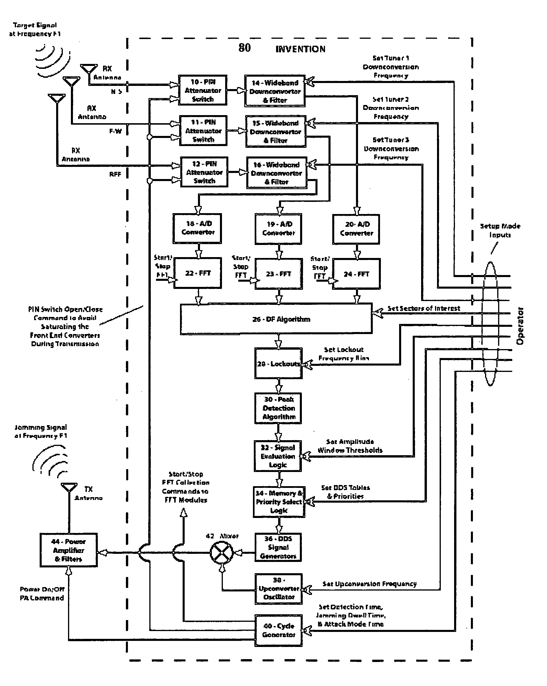
[0020] It is an object of the present invention to provide a method to automatically detect and jam sudden, short duration communications signals in near real time, from any selectable direction from the user on the battlefield. Such a system is unique in the number and type of input parameters it uses to allow the operator to tailor its jamming results. Such a system solves the efficiency, fratricide, and latency issues of prior art systems. Such a system greatly enhances the operational capabilities of the modern military unit, by allowing the unit to kill all enemy transmitters in any specified sector of the battlefield. The system should embody the addition of real time direction-finding methods to the invention of application Ser. No. 10 / 912,976
[0021] The preferred system should first have all the abilities of the system described by the previous patent application. Secondly the preferred system should be able to automatically detect the direction of the incoming signals (relative to the user), to add that information to the jamming decision logic. Finally, the preferred system should provide a user interface so that operators can set up the system to jam on enemy signals based upon their direction, thereby enhancing efficiency.

Problems solved by technology

This creates a problem for those who want to detect and jam such transmissions as they happen so quickly.
Practically, it is not feasible to simply “splash” the radio frequency spectrum with random noise in order to jam such transmissions.
The reasons are that it requires an unpractical amount of power to apply sufficient RF energy to wash out all transmissions.
Also, since the duration of the target transmissions is so short, it is not practical to have (for instance) a CPU that is programmed to evaluate signals, make a determination, and then command transmitters to jam.
There is simply not enough time to engage the frequency hopping signals before they have moved on to a new frequency.
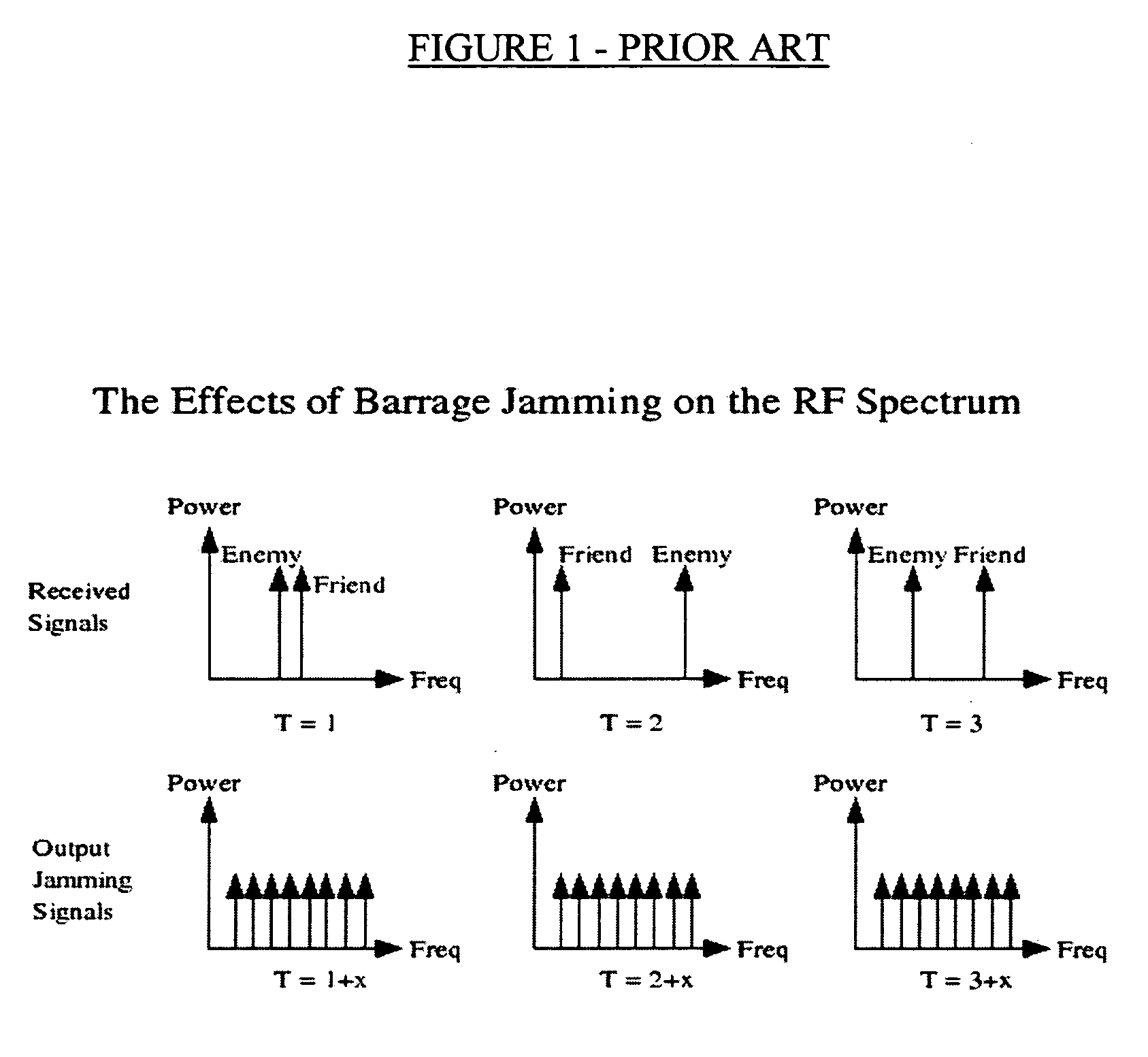
Barrage jamming is impractical for several reasons, including the amount of power needed to apply sufficient RF energy to wash out all transmissions.
This is extremely inefficient, since jamming energy is often applied to areas of the RF spectrum where there is no enemy communications traffic, thus the energy is wasted.
Also, fratricide of friendly transmissions that are near to the enemy communications is another problem of barrage jamming.
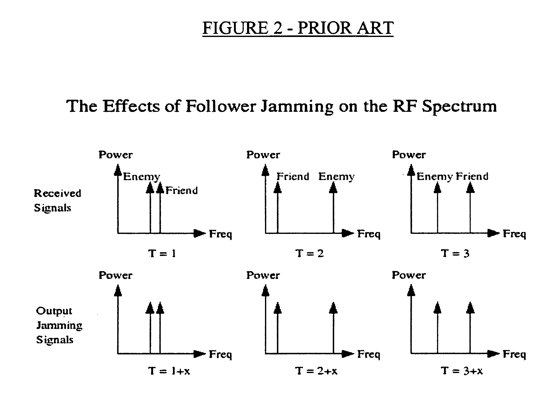
Follower jamming also has the drawback that any and all signals detected within its dynamic range will be jammed, regardless of whether it is emanating from a friend or from an enemy.
Thus, there are fratricide issues and inefficiency issues with wasting jammer signal energy on friendly communications.
Prior to the present invention, however, no follower jammer was responsive and / or had surgical accuracy adequate to truly defeat frequency-hopping transmitters.
But this simple system has several drawbacks including the fact that a massive amount of RF power is necessary to splash any sufficiently wide segment of the RF spectrum.
As the figure shows, an overwhelming percentage of this power is wasted.
Another drawback is that any friendly transmissions in the segment of focus will also be jammed.
A third drawback is that the power of the jamming signals is usually lower than the target signal, so that the target signal may not actually be disrupted at all.
This system solves the power issues of the barrage jamming system, but it has its own drawbacks.
The main drawback of the follower jamming system is the fratricide problem pictured here.
As a result, while the follower jammer is jamming enemy communications, friendly communications are also jammed, just like the barrage jamming system.

Method used


Image

  • Method and apparatus for surgical high speed follower jamming based on selectable target direction
  • Method and apparatus for surgical high speed follower jamming based on selectable target direction
  • Method and apparatus for surgical high speed follower jamming based on selectable target direction

Examples


Embodiment Construction

[0027] The following description is provided to enable any person skilled in the art to make and use the invention and sets forth the best modes contemplated by the inventor of carrying out his invention. Various modifications, however, will remain readily apparent to those skilled in the art, since the generic principles of the present invention have been defined herein specifically to provide a Method and Apparatus for Surgical High-speed Follower Jamming Based on Selectable Target Direction.

[0028] This invention of this patent application creates surgical follower jamming that is efficient and precise. It does so by employing a unique process that includes the addition of an internal direction-finding capability during normal operations. This invention thus focuses the jamming system on certain, specified compass sectors during its operation. Even less power may be needed during jamming operations due to the fact that only enemy signals coming from pre-defined directions will be...


PUM


Abstract

A Method and Apparatus for Surgical High-speed Follower Jamming Based on Selectable Target Direction is disclosed. The system and method of the present invention automatically detects and jams sudden, short duration communications signals in near real time, in a compass direction selected by the user on the battlefield. Such a system is unique in the number and type of input parameters it uses to allow the operator to tailor its jamming results. The system solves the efficiency, fratricide, and latency issues of prior art systems and greatly enhances the operational capabilities of the modem military unit by allowing the unit to kill all enemy transmitters in any specified sector of the battlefield. The system embodies the addition of real time direction-finding methods to the invention of application Ser. No. 10 / 912,976. The system has all the abilities of the system described in the '976 application, but is further able to automatically detect the direction of the incoming signals (relative to the user), and thereafter to add that information to the jamming decision logic. Finally, the preferred system provides a user interface that enables operators to set up the system to jam on enemy signals based upon the direction to those enemy signals.

Description

[0001] This application is a continuation-in-part of application Ser. No. 10 / 912,976, filed Aug. 6, 2004, now pending. [0002] This application is filed within one year of, and claims priority to Provisional Application Ser. No. 60 / 600,645, filed Aug. 11, 2004.BACKGROUND OF THE INVENTION [0003] 1. Field of the Invention [0004] This invention relates to advanced military grade communications jamming systems and, more specifically, to a Method and Apparatus for Surgical High Speed Follower Jamming Based on Selectable Target Direction. [0005] 2. Description of Related Art [0006] Modern military grade communication systems today employ short, burst type transmissions that constantly cycle through a secret sequence of frequencies in order to prevent detection and jamming. Such systems are commonly known as frequency hoppers. Typically, these systems (both foreign and domestic) only transmit on a particular frequency for no more than a few milliseconds at the most. This creates a problem f...

Claims


Application Information

Patent Timeline
IPC IPC(8): H04B1/69
CPCH04K3/41H04K3/42H04K3/45
Inventor KARLSSON, LARS
Owner AGILENT TECH INC
Learn More