
Optical laminate

Active Publication Date: 2006-07-13
DAI NIPPON PRINTING CO LTD
View PDF2 Cites 2 Cited by
  • Summary
  • Abstract
  • Description
  • Claims
  • Application Information

AI Technical Summary

Benefits of technology

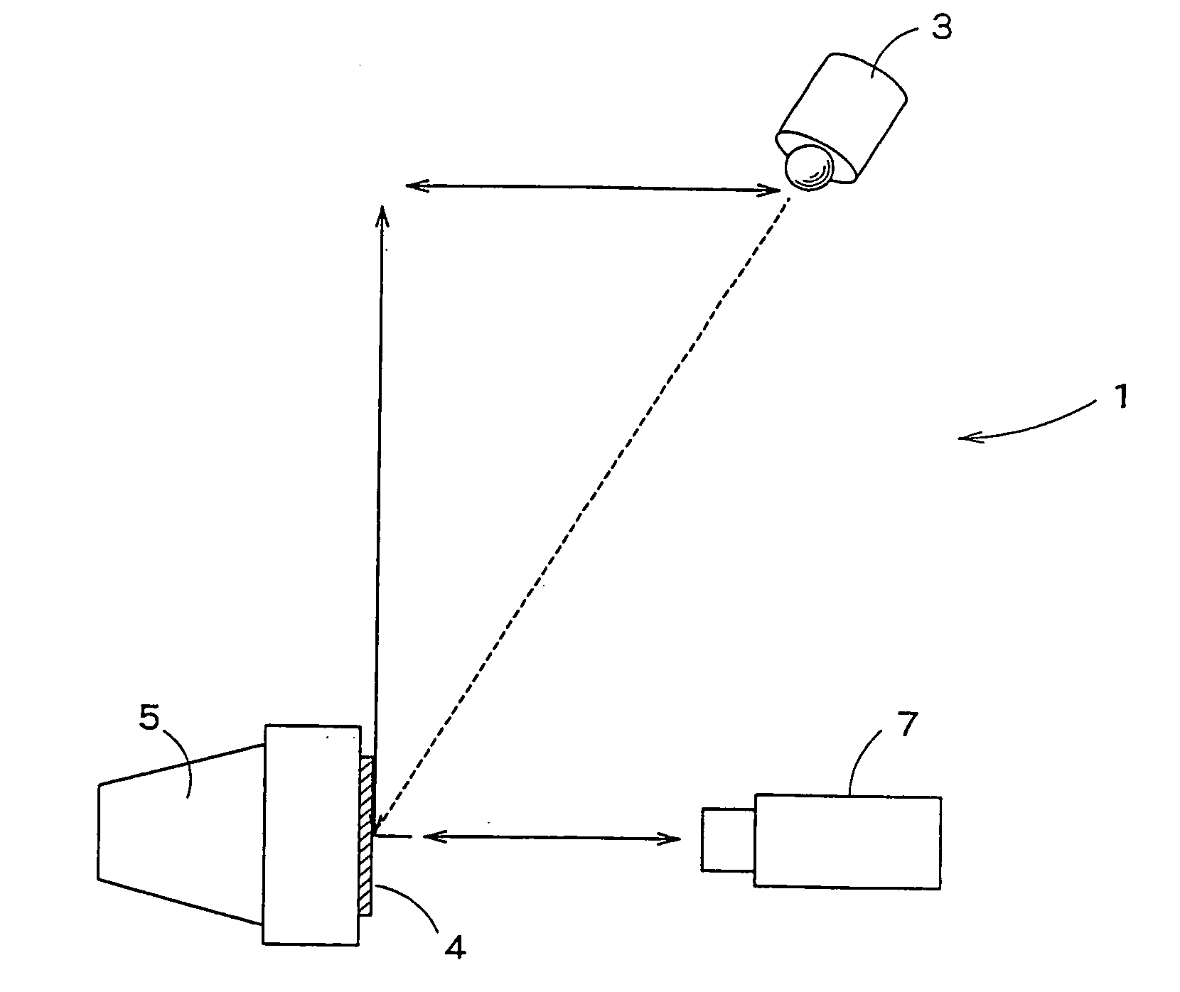
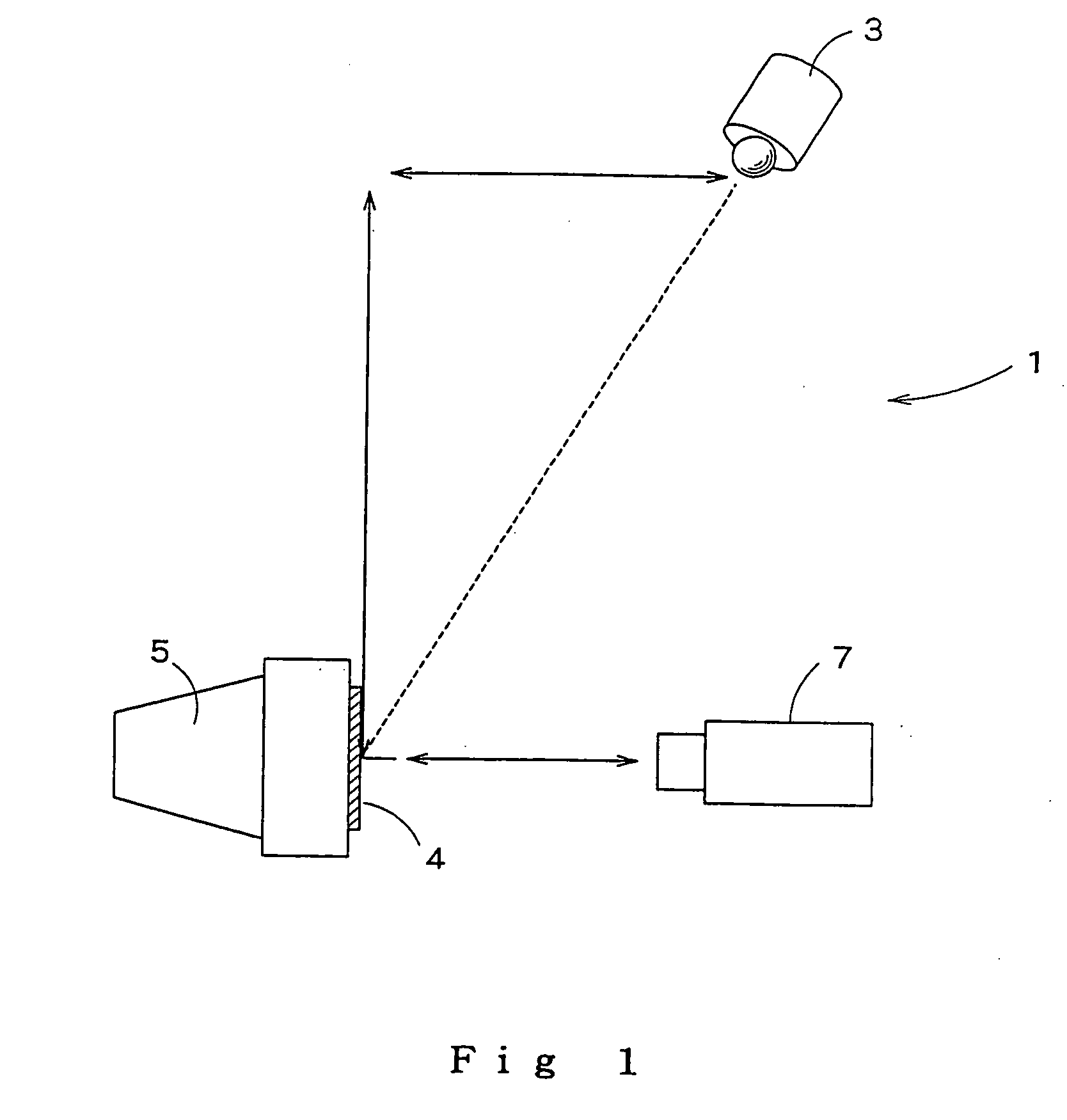
[0008] At the time of the present invention, the present inventors have found that excellent contrast and image visibility can be realized by bringing the black luminance and total light transmittance of an optical laminate to respective specific numerical ranges. Accordingly, an object of the present invention is to provide an optical laminate, which has excellent antireflection function and improved image display properties, by focusing attention to the luminance and total light transmittance in an optical laminate and bringing the luminance value and the total light transmittance to respective specific ranges.

Problems solved by technology

For image display devices using a fluorescent substance, it has been often pointed out that, due to high reflectance of the fluorescent substance, reflection of external light from the surface of the display device occurs resulting in lowered visibility of displayed images.
However, it has been often pointed out that, since the fluorescent substance in the image display device is white, the reflectance is so high that external light-derived reflected light is likely to occur and, further, reflected light often occurs as scattered light within the optical laminate and the fluorescent substance in the image display device and, as a result, these reflected light and scattered light affect luminescent color from the fluorescent substance, making it impossible to provide images possessing excellent contrast (particularly black reproduction) and light transmission.
Since, however, the colored material (layer) per se has low transmittance, the total light transmittance is disadvantageously lowered to about 50 to 70% and, consequently, image reproduction is often lowered.

Method used


Image

  • Optical laminate
  • Optical laminate

Examples


example 1

[0143] A polyethylene terephthalate (PET) film (manufactured by Toray Industries, Inc., #100-U46, thickness 100 μm) was provided. A composition 1 for an antistatic agent-containing hardcoat layer was bar coated onto a surface of this film. Thereafter, the solvent was removed by drying, and ultraviolet light was then applied to the coating with an ultraviolet irradiation apparatus (Fusion UV Systems Japan KK, light source H bulb) at an exposure of 108 mJ / m2 to cure the coating and thus to form a 10 μm-thick ATO-containing hardcoat layer.

[0144] Next, a composition 2 for a lower-refractive index layer was bar coated onto the surface of the ATO-containing hardcoat layer. The coating was dried to remove the solvent from the coating, and ultraviolet light was then applied to the coating with an ultraviolet irradiation apparatus (Fusion UV Systems Japan KK, light source H bulb) at an exposure of 192 mJ / m2 to cure the coating and thus to prepare an optical laminate. The layer thickness was...

example 2

[0145] An optical laminate was prepared in the same manner as in Example 1, except that the composition 1 for an antistatic agent-containing hardcoat layer was changed to the composition 2 for an antistatic agent-containing hardcoat layer, and the thickness of the antistatic agent-containing hardcoat layer was changed to 3 μm.

example 3

[0146] An optical laminate was prepared in the same manner as in Example 1, except that the composition 1 for an antistatic agent-containing hardcoat layer was changed to the composition 3 for an antistatic agent-containing hardcoat layer, and the thickness of the antistatic agent-containing hardcoat layer was changed to 5 μm.


PUM

PropertyMeasurementUnit
Thicknessaaaaaaaaaa
Thicknessaaaaaaaaaa
Thicknessaaaaaaaaaa

Abstract

The present invention disclosed an optical laminate that can realize excellent contrast and image visibility. The optical laminate comprises: a light transparent base material; and an antistatic agent-containing hardcoat layer and a lower-refractive index layer provided in that order on the light transparent base material, wherein the optical laminate has a black luminance of not more than 9.3 cd / m2, and the optical laminate has a total light transmittance of not less than 80% and not more than 94%.

Description

RELATED APPLICATION [0001] This application is a patent application claiming priority based on Japanese Patent Application Nos. 286485 / 2004 and 316756 / 2004, the whole of which is incorporated herein. TECHNICAL FIELD [0002] The present invention relates to an optical laminate having improved image visibility and contrast. BACKGROUND ART [0003] In image display apparatuses using a fluorescent substance, for example, cathode-ray tube display devices (CRTs), plasma displays (PDPs), vacuum fluorescent displays, and field emission-type displays, for example, an electron beam or ultraviolet light is applied to the fluorescent substance to cause fluorescent emission of the fluorescent substance, and an image is displayed by taking advantage of transmitted light or reflected light from the fluorescent screen. [0004] For image display devices using a fluorescent substance, it has been often pointed out that, due to high reflectance of the fluorescent substance, reflection of external light fr...

Claims


Application Information

Patent Timeline
IPC IPC(8): G01N21/88H01J29/88
CPCH01J29/896Y10T428/31507Y10T428/31616Y10T428/31623B32B7/02G02B1/11H01J11/44
Inventor NAKASHIMA, MASATAKAHIRAI, TAKESHI
Owner DAI NIPPON PRINTING CO LTD
Learn More