
Brake system for straddle-type vehicle

Active Publication Date: 2006-07-13
YAMAHA MOTOR CO LTD
View PDF5 Cites 24 Cited by
  • Summary
  • Abstract
  • Description
  • Claims
  • Application Information

AI Technical Summary

Benefits of technology

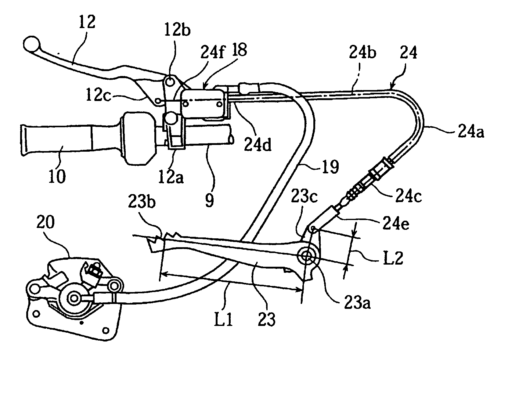
[0010] The force applied to the brake pedal is transmitted by cable rather than by a hydraulic system, thereby reducing the cost of the brake system and simplifying its construction. This configuration also provides for increased flexibility regarding the layout of vehicle components around the brake pedal and the brake system. Additionally, because a rider usually has less sensitivity when operating the foot pedal as compared to a hand lever to an increase in operational force required and increased slop in the cable due to stretching, more riders will feel comfortable using either the foot pedal or the hand lever to operate the vehicle brakes. Moreover, the rider experiences a stiffer feeling (i.e., a more responsive feeling) when operating the brake system using the brake lever because the brake lever interacts with the force actuator without the force being transmitted through a cable.
[0013] In a preferred embodiment, the brake system also includes a brake pedal. The brake pedal and the brake lever, more preferably, can operate independently of each other to move the force actuator and operate the brake system. In this manner, the brake lever do not have to also move the brake pedal when moving the force actuator, and vise versa.

Problems solved by technology

Some riders dislike the feel of such systems when a hand lever is used to operate the brake.
Additionally, it may become harder to squeeze the brake lever as the wire cable becomes dirty and warn.

Method used


Image

  • Brake system for straddle-type vehicle
  • Brake system for straddle-type vehicle
  • Brake system for straddle-type vehicle

Examples


first embodiment

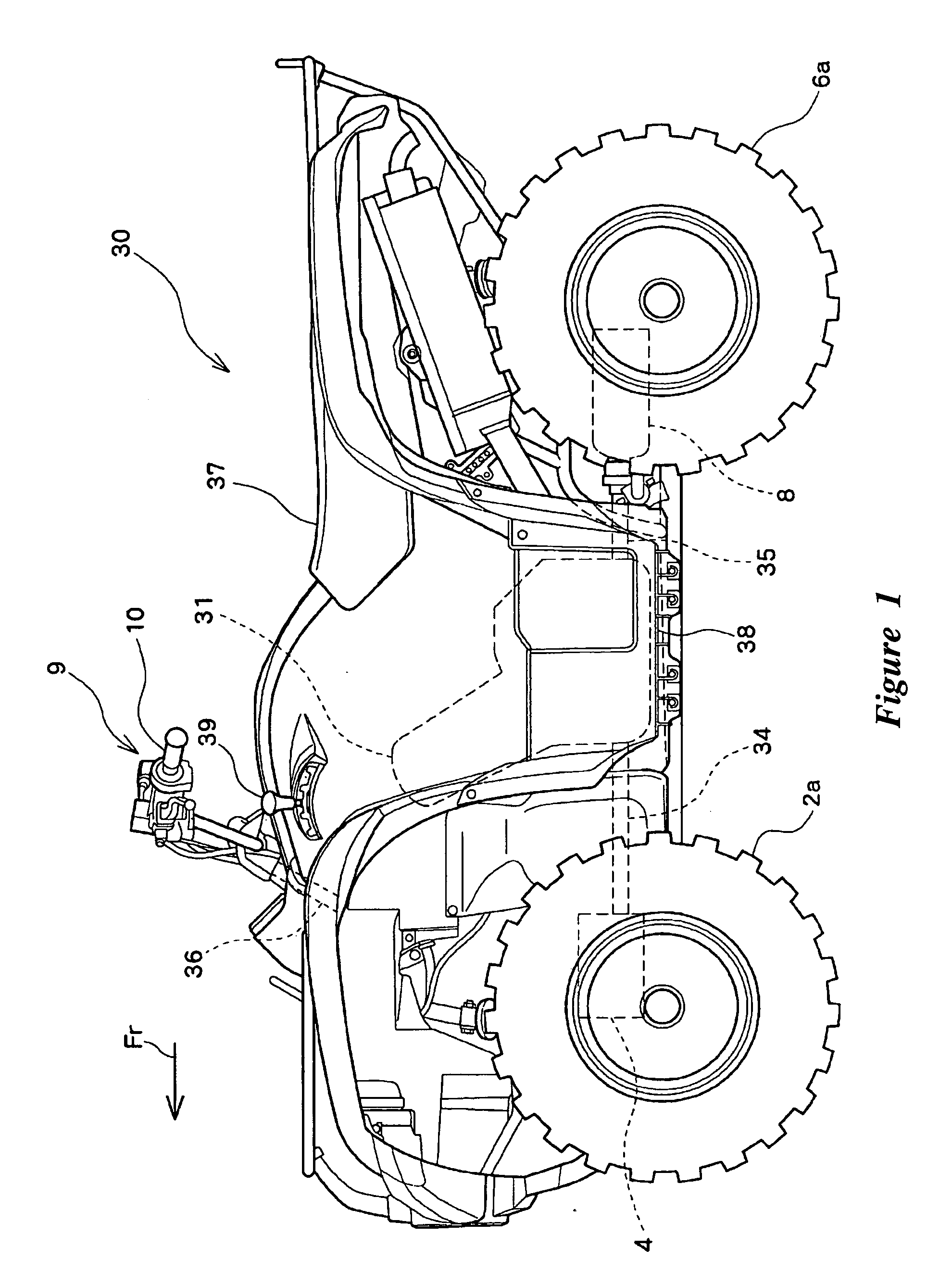
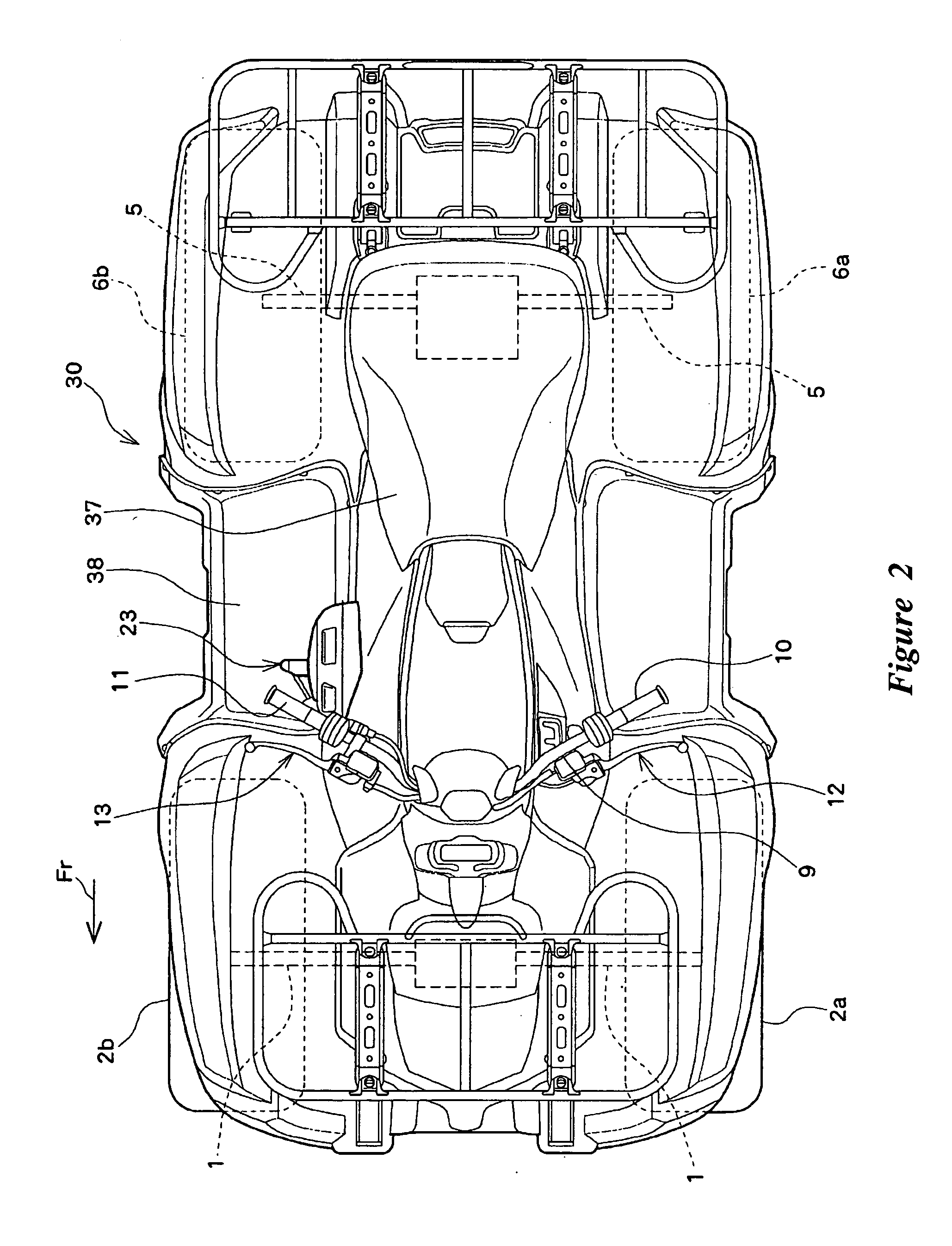
[0026] Embodiments of the invention will be described below with reference to the drawings. FIG. 1 is a side view showing a small-sized four-wheel vehicle 30 being an example of a straddle-type vehicle that includes a vehicular brake system configured in accordance with the invention. FIG. 2 is a plan view showing the small-sized four-wheel vehicle 30. While the present brake system is illustrated in the context of an all-terrain vehicle, the brake system and aspects and features thereof can be used with other types of vehicles as well, including, without limitation, motorcycles, scooters, motorized bicycles, and the like.

[0027] The small-sized four-wheel vehicle 30 is a rough terrain traveling vehicle used for sport traveling on a rough terrain, for farm work, or for like purposes. The small-sized four-wheel vehicle 30 comprises an engine unit 31 preferably arranged centrally within a vehicle body. The engine unit 31 preferably includes an internal combustion engine and a variable ...

second embodiment

[0065] The second embodiment is constructed so that a braking force is applied to front wheels 2a, 2b even when either the front wheel brake lever 13 or a brake pedal 23 is manipulated. Also, in the case where the brake pedal 23 is manipulated, a braking force is also applied to rear wheels 6a, 6b in addition to braking of the front wheels 2a, 2b.

[0066] Arranged in the vicinity of the brake pedal 23 is a rear wheel master cylinder 28 that generates hydraulic pressure when the brake pedal 23 is operatively turned (e.g., depressed). The rear wheel master cylinder 28 is connected through a hydraulic hose (brake hose) 29, a branch joint 29a, and branch pipes 29b, 29c to left and right rear wheel brake calipers 20, 21.

[0067] With the brake system according to the second embodiment, when the front brake lever 13 is operated (e.g., squeezed); a front wheel master cylinder 14 generates hydraulic pressure in the same manner as in the first embodiment to apply a braking force to the front w...


PUM


Abstract

An improved brake system is provided for a vehicle including at least front and rear wheels. The brake system comprises a braking force generating mechanism, a brake lever assembly and a foot-operated brake pedal. The brake force generating mechanism applies a braking force to at least a front wheel or a rear wheel of the vehicle. The brake lever assembly includes a hand-operated lever and a force actuator. The force actuator moves between at least first and second positions so as to selectively actuate the brake force generating mechanism to produce a braking force. The force actuator interacts with the hand-operated lever such that movement of the hand-operated lever moves the force actuator from the first position to at least the second position. The force actuator also interacts with the brake pedal, which are coupled together by a cable. Movement the brake pedal also moves the force actuator from the first position to the second position.

Description

CROSS-REFERENCE TO RELATED APPLICATIONS [0001] This application is based on and claims priority under 35 U.S.C. § 119(a)-(d) to Japanese Patent Application No. 2004-368909, filed Dec. 21, 2004, and to Japanese Patent Application No. 2005-334940, filed Nov. 18, 2005, the entire contents of which are hereby incorporated by reference. BACKGROUND OF THE INVENTION [0002] 1. Field of the Invention [0003] The present invention relates to a vehicular brake system comprising a braking force generating mechanism that generates a braking force when either a brake lever or a brake pedal is operated. [0004] 2. Description of the Related Art [0005] Brake systems for motorcycles, scooters, ATVs, and the like often include a brake lever, a master cylinder, and one or more sets of brake calipers and brake discs associated with one or more wheels of the vehicle. For example, with a hydraulic brake system, such as the type disclosed in Japanese Patent Publication No. JP-A-2001-88766, when the front br...

Claims


Application Information

Patent Timeline
IPC IPC(8): B60T13/00
CPCB62L3/023B62L3/04B62L3/08
Inventor TAKEUCHI, HITOSHI
Owner YAMAHA MOTOR CO LTD
Learn More