
Electron microscope and a method of imaging objects

Inactive Publication Date: 2006-07-13
NAT UNIV OF SINGAPORE
View PDF4 Cites 10 Cited by
  • Summary
  • Abstract
  • Description
  • Claims
  • Application Information

AI Technical Summary

Benefits of technology

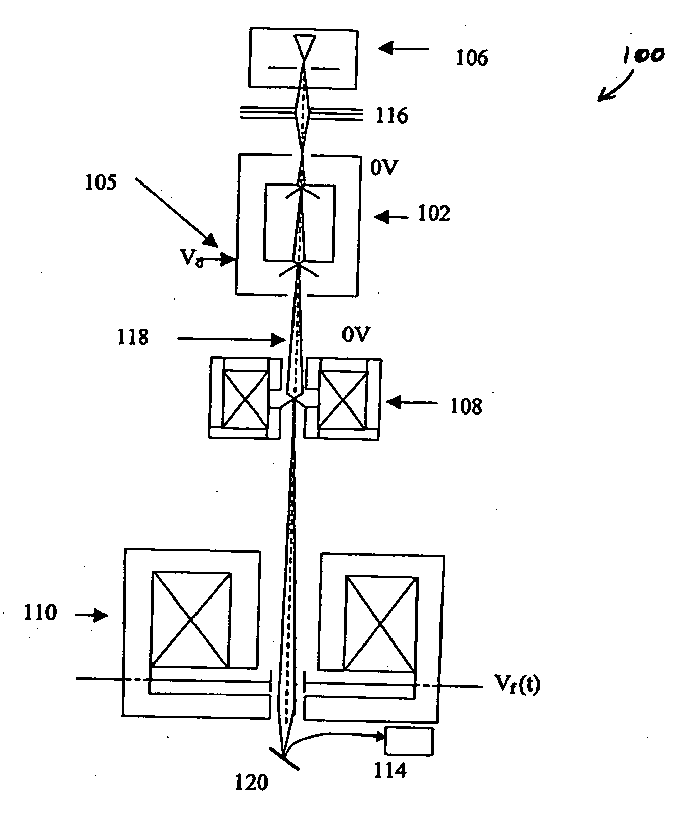
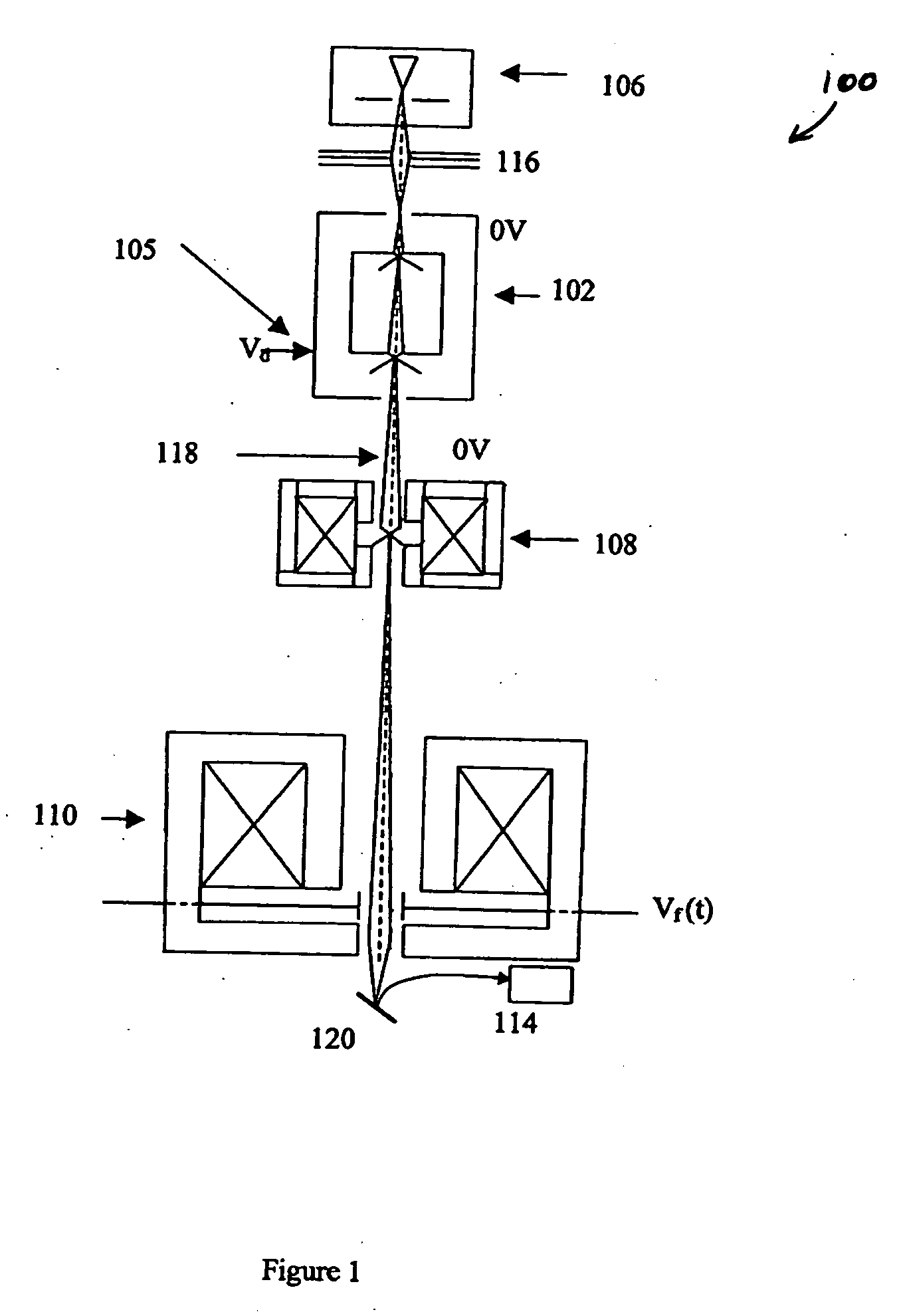
[0010] The method may further comprise the step of providing a drift tube for slowing each electron pulse to enhance spatial separation of the electrons in each electron pulse.
[0021] The electron microscope may further comprise an axis between said electron source and said object, and a drift tube juxtaposed about said axis adapted for slowing each electron pulse to enhance spatial separation of the electrons in each electron pulse.

Problems solved by technology

An ideal lens would demagnify the primary beam of electrons into a perfect point at the specimen, an infinitely small probe, however, in practice, lens aberrations limit the probe to be a finite spot.

Method used


Image

  • Electron microscope and a method of imaging objects
  • Electron microscope and a method of imaging objects
  • Electron microscope and a method of imaging objects

Examples


Embodiment Construction

[0036] Although the following text sets forth a detailed description of numerous different embodiments of the invention, it should be understood that the legal scope of the invention is defined by the words of the claims set forth at the end of this patent. The detailed description is to be construed as exemplary only and does not describe every possible embodiment of the invention since describing every possible embodiment would be impractical, if not impossible. Numerous alternative embodiments could be implemented, using either current technology or technology developed after the filing date of this patent, which would still fall within the scope of the claims defining the invention.

[0037] It should also be understood that, unless a term is expressly defined in this patent using the sentence “As used herein, the term ‘______° is hereby defined to mean . . . ” or a similar sentence, there is no intent to limit the meaning of that term, either expressly or by implication, beyond i...


PUM


Abstract

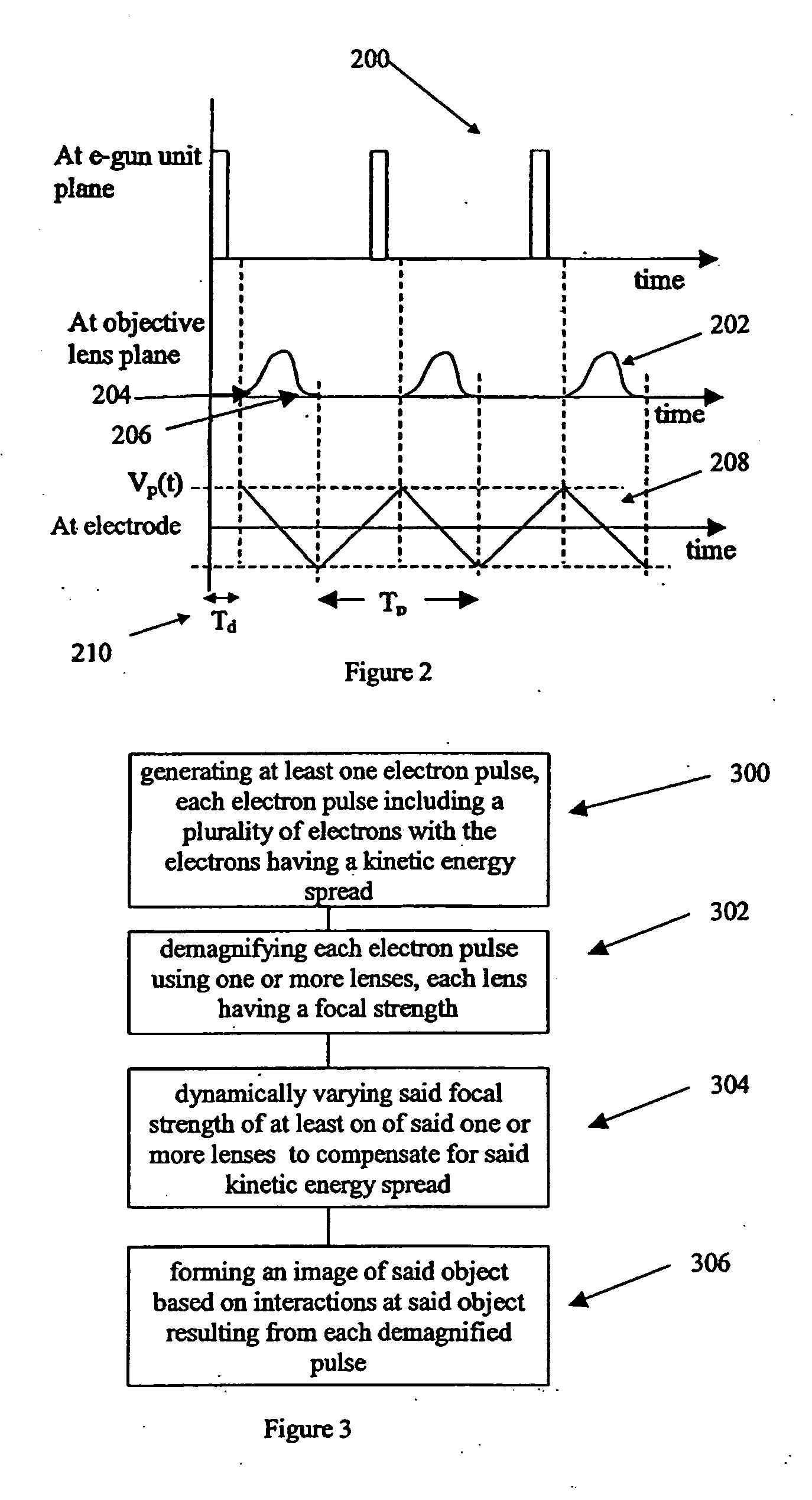
An electron microscope and a method of imaging objects. The method including the steps of: generating at least one electron pulse, each electron pulse including a plurality of electrons with the electrons having a kinetic energy spread; demagnifying each electron pulse using one or more lenses, each lens having a focal strength; dynamically varying said focal strength of at least one of said one or more lenses to compensate for said kinetic energy spread; and forming an image of said object based on interactions at said object resulting from each demagnified pulse. The electron microscope comprising: an electron source adapted to produce a plurality of electron pulses, each electron pulse including a plurality of electrons with the electrons having a kinetic energy spread; one or more lenses adapted to demagnify each of said electron pulses at said object, each lens having a focal strength; compensation means for dynamically varying said focal strength of at least one of said one or more lenses to compensate for said kinetic energy spread; and a detector for forming an image of said object based on interactions at said object resulting from each of said demagnified pulses

Description

REFERENCE TO RELATED APPLICATION [0001] This application claims priority from Provisional Application Ser. No. 60 / 631,769, filed on Nov. 29, 2004, which is expressly incorporated by reference herein.FIELD OF INVENTION [0002] The invention relates to an electron microscope and a method of imaging objects. BACKGROUND OF THE INVENTION [0003] Electron microscopes are used to image objects on a very small scale, to overcome limitations in light microscopes. For example Scanning Electron Microscopy (SEM) involves imaging an object of interest by generating a demagnified beam of electrons at an object and detecting the interactions. Interactions may take the form of “secondary electrons” from inelastic interaction, “backscatter electrons” from elastic interactions, x-rays and Auger electrons. Other signals that maybe detected include plasmons, phonons, bremsstrahlung radiation, and cathodoluminescence. [0004] In an SEM type microscope an electron gun emits and accelerates a beam of electro...

Claims


Application Information

Patent Timeline
IPC IPC(8): G21K7/00
CPCH01J37/153H01J37/21H01J37/265H01J37/28H01J2237/0432H01J2237/1202H01J2237/1534H01J2237/21H01J2237/2485H01J2237/2538H01J2237/2809
Inventor KHURSHEED, ANJAM
Owner NAT UNIV OF SINGAPORE
Learn More