
Apparatus and method for acquiring time-resolved measurements utilizing direct digitization of the temporal point spread function of the detected light

a technology of temporal point spread function and time-resolved measurement, applied in the field of time-resolved optical imaging system, can solve the problems of 50 fundamentally inefficient approach, and 20 tpsfs to be sampled, and achieve the effect of reducing the time of data acquisition

Inactive Publication Date: 2006-07-06
IMAGING DIAGNOSTIC SYST
View PDF9 Cites 7 Cited by
  • Summary
  • Abstract
  • Description
  • Claims
  • Application Information

AI Technical Summary

Benefits of technology

[0023] It is an object of the present invention to reduce data acquisition time in a time-resolved optical imaging system by directly digitizing the temporal point spread function.
[0024] It is another object of the present invention to increase the signal-to-noise ratio of the data obtained from a time-resolved optical imaging system by directly digitizing the temporal point spread function and averaging several TPSFs.

Problems solved by technology

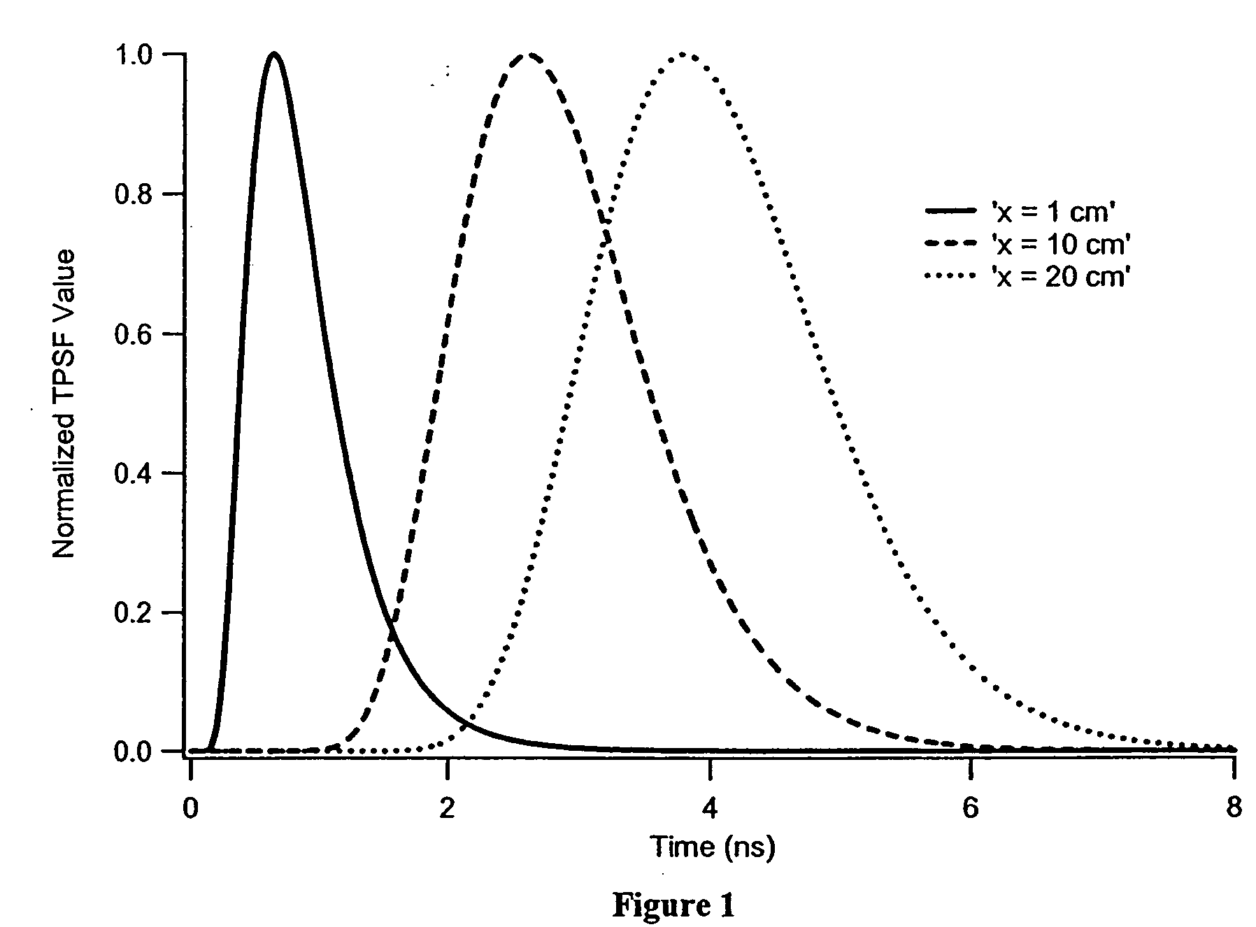
The disadvantage of this approach is that if 50 samples are required across the TPSF to adequately characterize it, then 50 TPSFs must be sampled.
This approach is fundamentally inefficient.
The disadvantage of this approach is that if 20 samples are required across the TPSF to adequately characterize it, then 20 TPSFs must be sampled.
This approach is fundamentally inefficient.
This has the disadvantage of being very slow.
The disadvantage of this approach is the extremely high cost and fragility of streak cameras, limiting this approach to laboratory conditions.

Method used


Image

  • Apparatus and method for acquiring time-resolved measurements utilizing direct digitization of the temporal point spread function of the detected light
  • Apparatus and method for acquiring time-resolved measurements utilizing direct digitization of the temporal point spread function of the detected light
  • Apparatus and method for acquiring time-resolved measurements utilizing direct digitization of the temporal point spread function of the detected light

Examples


Embodiment Construction

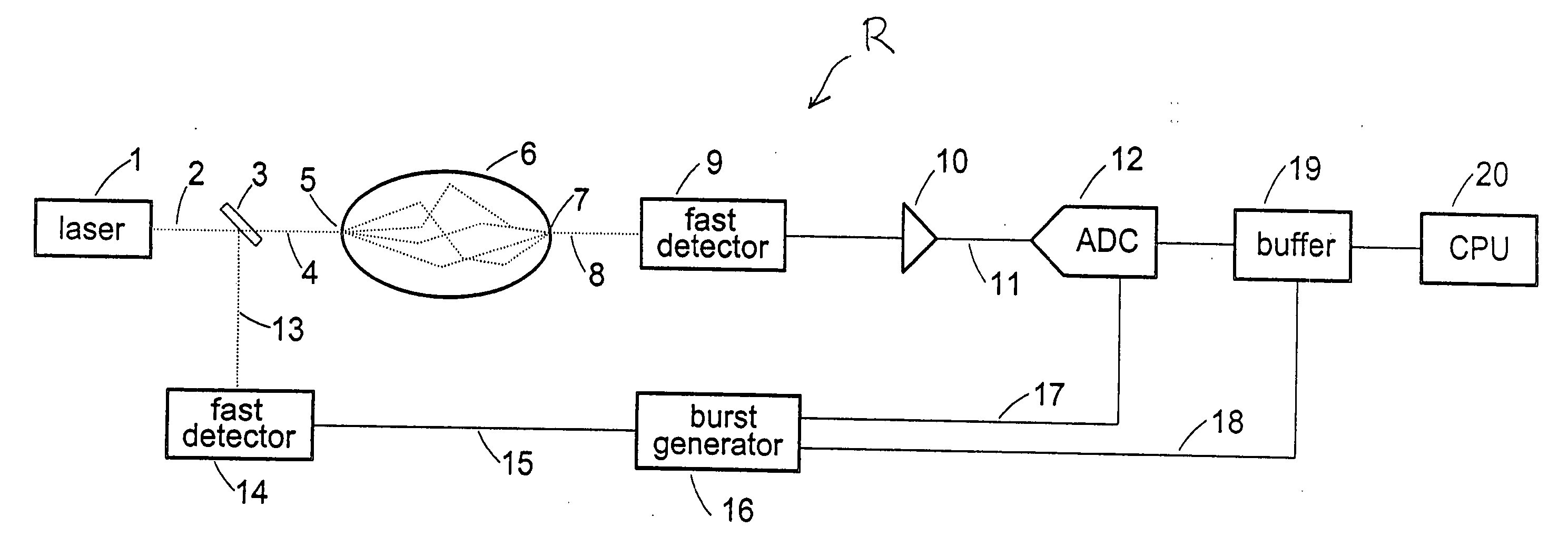
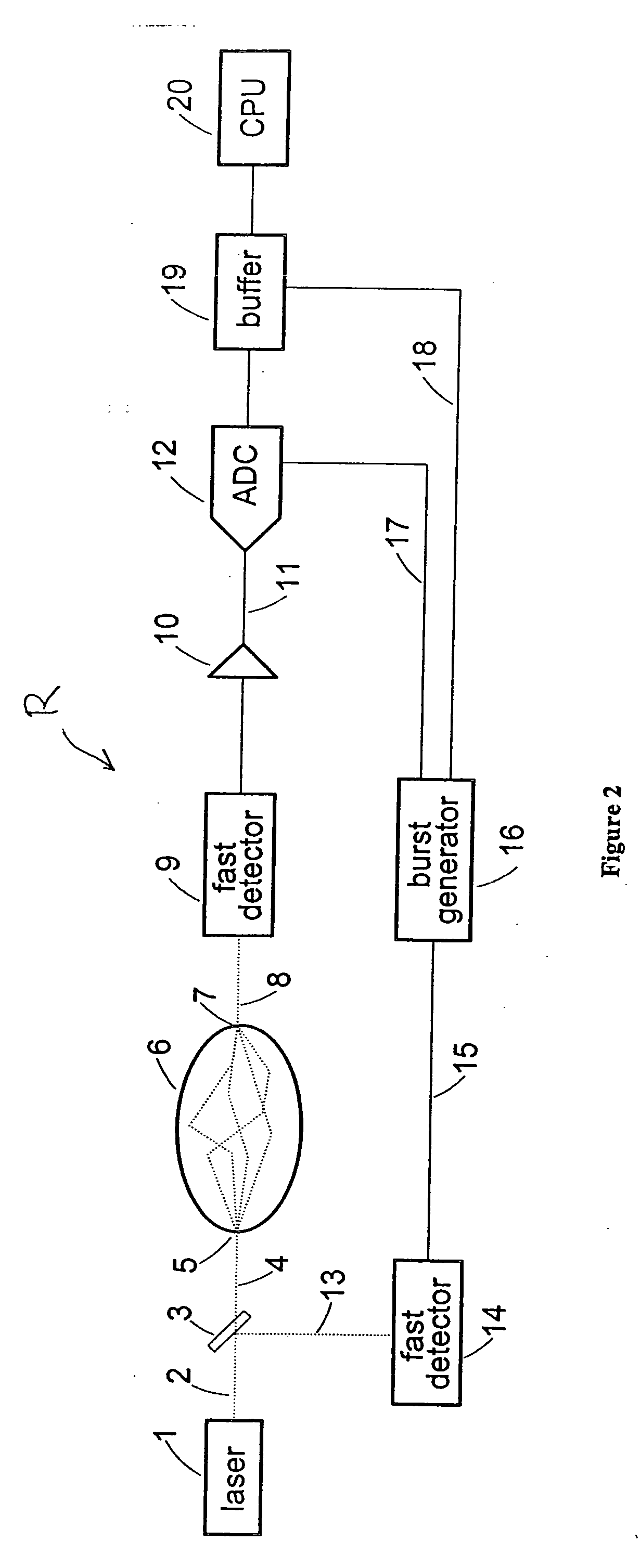
[0034] Referring to FIG. 2, a time-resolved optical measurement system R made in accordance with the present invention is disclosed. A laser 1 produces extremely short, but intense, light pulses 2. Mode-locked Ti-Sapphire lasers have pulse widths in the sub-picosecond range and regeneratively-amplified mode-locked lasers have pulse widths, without compression, in the 10 s-100 s of picoseconds. Fast pulsed diode lasers can also achieve pulse widths well less than 1 nanosecond. The laser output 2 is a periodic light pulse, with pulse width in the femtosecond or picosecond range and repetition rates typically kilohertz to megahertz. A beamsplitter 3 sends most of the light as beam 4 to subject 6, as for example, a female breast. A small portion of the light is reflected as beam 13. Beam 4 enters the subject at location 5 and undergoes multiple scatterings and absorptions. A portion of the incident light ultimately exits the subject, for example at point 7, forming beam 8 and is detecte...


PUM


Abstract

An apparatus for acquiring time-resolved measurements from a sample from optical scanning comprises pulsed laser light directed to the sample; a first detector disposed to detect the light after exiting from the sample, the detected light being in the form of a first temporal point spread function (TPSF); a first amplifier to amplify the first TPSF; a first analog-to-digital converted (ADC) to directly digitize the first TPSF; a first buffer connected to the first ADC; a time-pickoff detector to initiate the first ADC to digitize the first TPSF; a clock burst generator initiated by the time-pickoff detector to provide conversion timing to the first ADC; and a computer programmed to fit the digitized first TPSF to a theoretical curve to extract its amplitude, and attenuation and scattering coefficients. A method for acquiring time-resolved measurements from a sample from optical scanning comprises directing a pulse of light onto a surface of the sample; detecting the light that exits from the sample in the form of a temporal point spread function (TPSF); directly digitizing the TPSF; and extracting a transport scattering coefficient and a absorption coefficient from the digitized TPSF.

Description

RELATED APPLICATION [0001] This is a nonprovisional application claiming the benefit of provisional application Ser. No. 60 / 627,147, filed Nov. 15, 2004, incorporated herein by reference.FIELD OF THE INVENTION [0002] The present invention relates generally to optical imaging systems and particularly to time-resolved optical imaging systems employing pulsed laser light. BACKGROUND OF THE INVENTION [0003] Many methods exist to nondestructively measure the composition of materials. For materials such as living tissue, x-ray is the oldest method of measurement. Differences in x-ray absorption result from differences in atomic number and differences in density. These differences can be measured by capturing a transmitted x-ray flux on a photographic medium or with an equivalent electronic detector, as in an x-ray computed tomographic scanner. Contrast agents can be introduced, typically with high atomic numbers such as iodine, to enhance features in the tissue. Nuclear tracers and radiop...

Claims


Application Information

Patent Timeline
Patent Type & Authority Applications(United States)
IPC IPC(8): A61B6/00
CPCA61B5/0059
Inventor WAKE, ROBERT H.PONDER, STEVEN L.
Owner IMAGING DIAGNOSTIC SYST
Learn More