Data erasing device using permanent magnet
- Summary
- Abstract
- Description
- Claims
- Application Information
AI Technical Summary
Benefits of technology
Problems solved by technology
Method used
Image
Examples
first embodiment
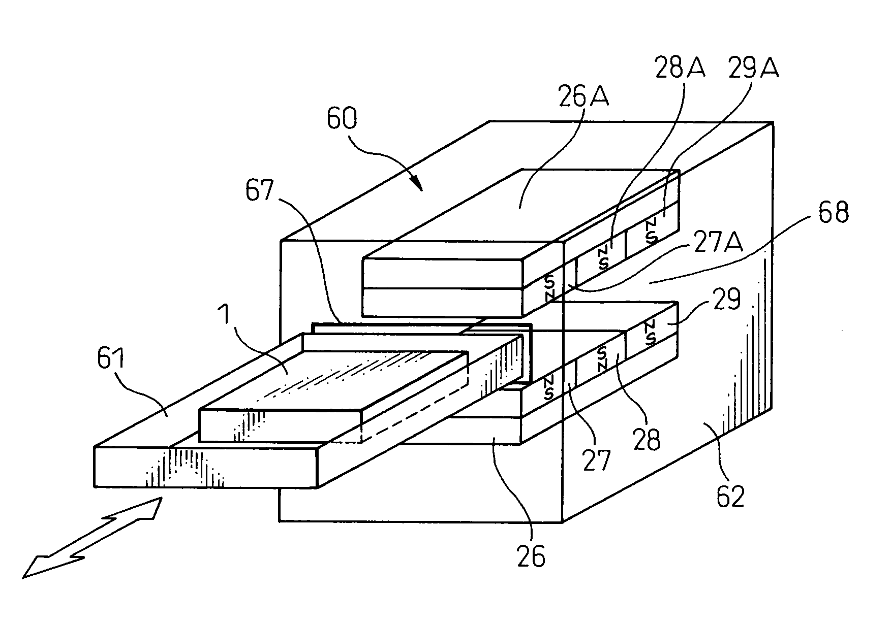
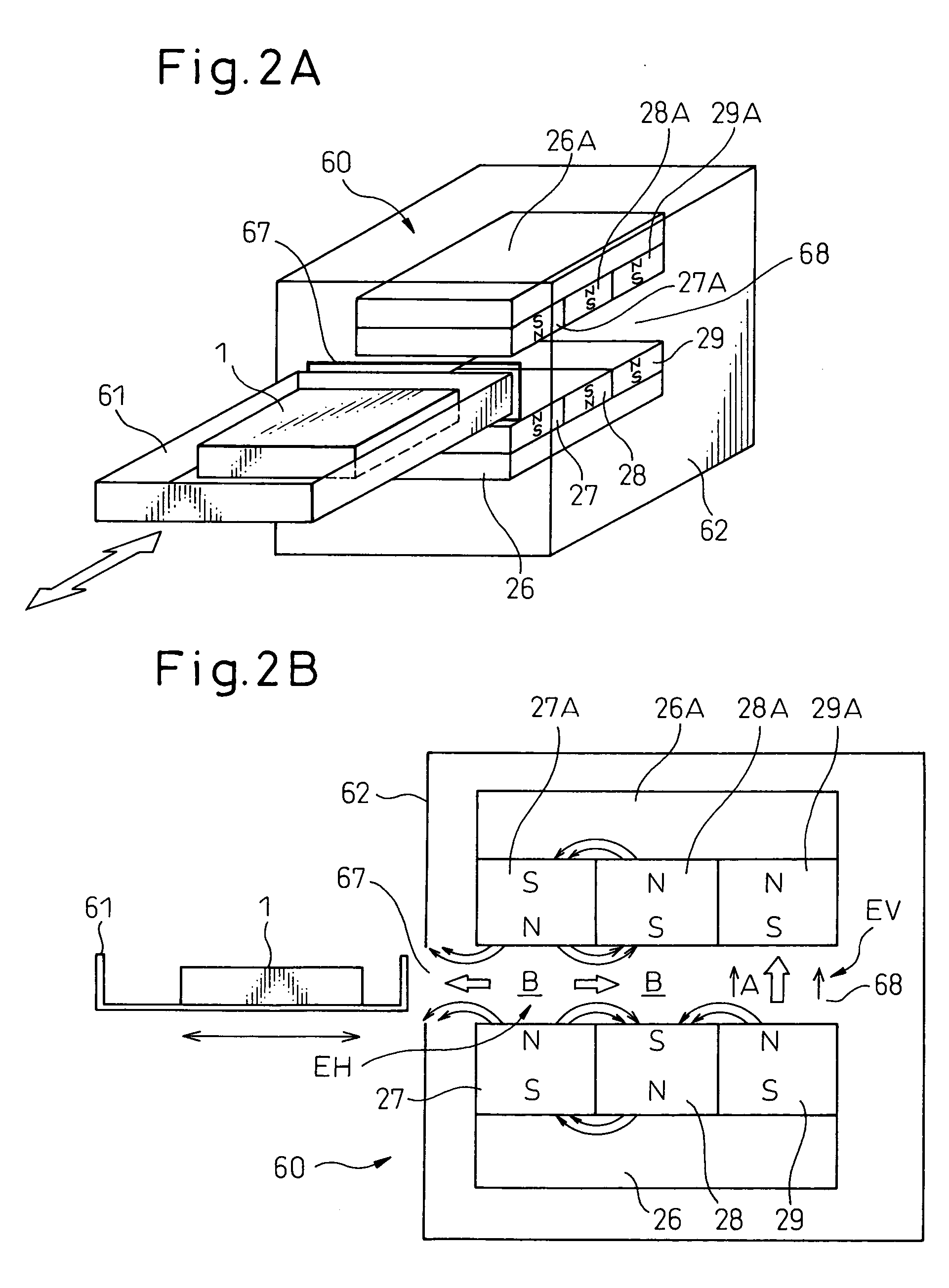
[0056]FIG. 3A shows a state that a magnetic disk device 1H onto which data is written by the horizontal recording system is inserted into the data erasing device 60 having the configuration as shown in FIG. 2. In FIG. 3A, a black arrowhead indicates a direction of a magnetic field, and an outline arrowhead indicates a moving direction of the disk device 1H. The magnetic disk device 1H onto which data is written by the horizontal recording system is passed through the data erasing area EH formed by the repulsive force of the magnets 27, 27A, 28, and 28A, by a predetermined number of times. Then, the magnetic disk 5 fitted to the spindle motor 3 of the magnetic disk device 1H passes through the magnetic field of the horizontal direction component in the data erasing area EH, so that the data written by the horizontal recording system is erased.
[0057]FIG. 3B shows a state that a magnetic disk device 1V onto which data is written by the vertical recording system is inserted into the da...
second embodiment
[0061] The slide tray 20 is configured to be able to slide on the main body 30. Therefore, the cross-sectional shape of the slide tray 20 in a direction orthogonal with the slide direction of the main body 21 is uniform. A knob 23 for sliding the swing tray 20 is provided at the front end of the main body 21. Grooves 22 for prescribing a stepwise slide position of the slide tray 20 to be described later are provided on the upper surface of the main body 21 at the front end at the knob 23 side. the number of the grooves 22 is four. A magnet fitting hole 25 is provided at a backend side of the main body 21 adjacent to the grooves 22. Two permanent magnets (a first magnetic field generating source, hereinafter simply called magnets) 27 and 28 that are fitted to the yoke 26 are provided at the back end side of the magnet fitting hole 25. A stopper protrusion 24 to be described later is provided on the side surface of the main body 21.
[0062] The magnets 27 and 28 fitted to the slide tra...
PUM
 Abstract
Description
Claims
Application Information
 - R&D
- Intellectual Property
- Life Sciences
- Materials
- Tech Scout
- Unparalleled Data Quality
- Higher Quality Content
- 60% Fewer Hallucinations
Browse by: Latest US Patents, China's latest patents, Technical Efficacy Thesaurus, Application Domain, Technology Topic, Popular Technical Reports.
© 2025 PatSnap. All rights reserved.Legal|Privacy policy|Modern Slavery Act Transparency Statement|Sitemap|About US| Contact US: help@patsnap.com


