
Method and system for health monitoring of aircraft landing gear

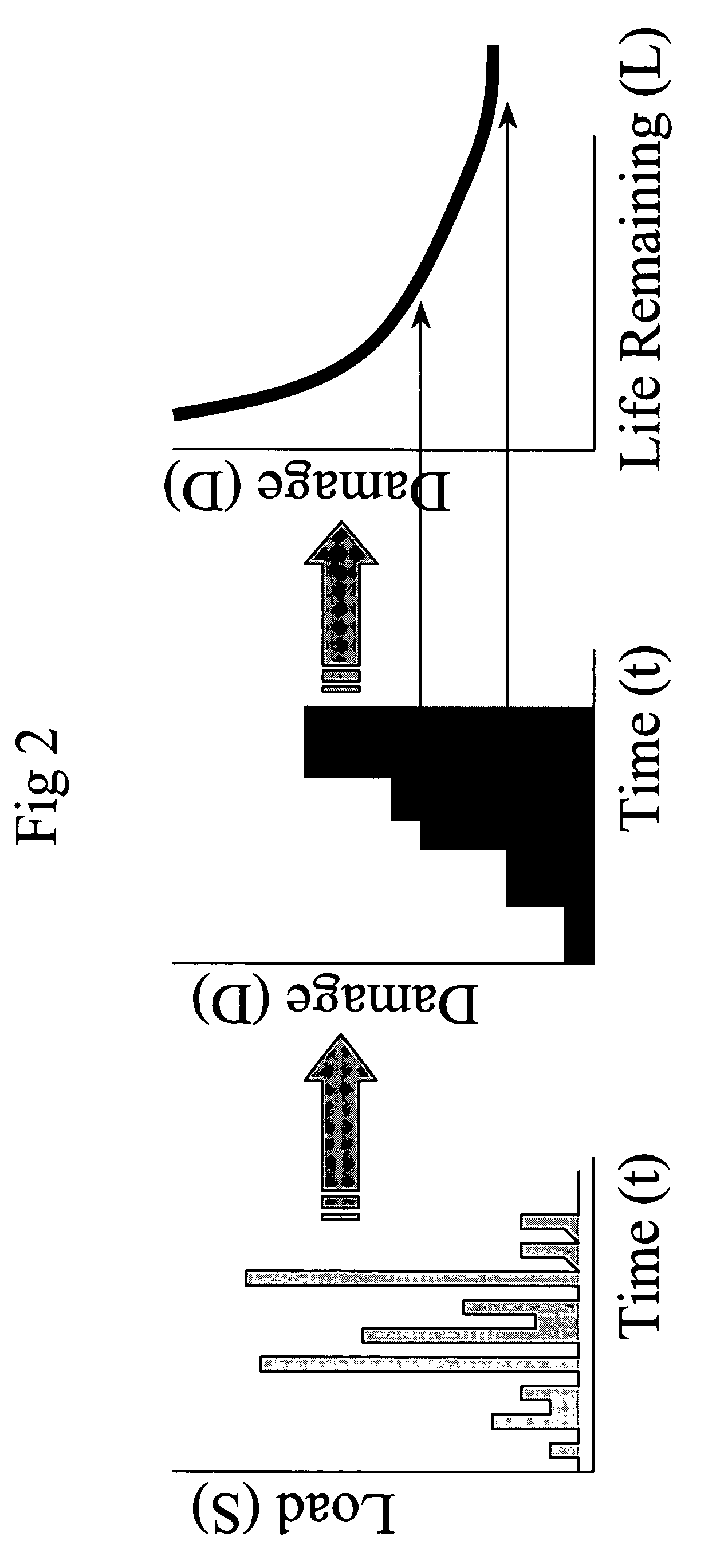
Inactive Publication Date: 2006-07-06
MESSIER DOWTY
View PDF15 Cites 113 Cited by
  • Summary
  • Abstract
  • Description
  • Claims
  • Application Information

AI Technical Summary

Benefits of technology

[0010] The present invention provides a system having a variety of sensors attached to the landing gear structure and equipment, a method and system to communicate the data measured by the sensors to the monitoring system, a method to analyze the data to derive rele

Problems solved by technology

Because of the lack of reliable quantitative data, errors are made in this assessment.
As a result, an airplane may be grounded unnecessarily, at a considerable cost of time and money, or conversely, a damaged airplane can continue in service, thus compromising public safety.
This results in some servicing and inspections taking place before it is required, thus resulting in considerable additional cost of time and money.
Conversely, in some cases, the landing gear may be in need of servicing, maintenance or replacement before the next scheduled time.
In the interests of the public safety, it is better to be safe than sorry and so maintenance and servicing schedules tend to be very conservative.
Landing gear health monitoring systems involve several unique issues that differentiate it from all other airplane systems and the airframe itself.
These aluminum structures can sustain fairly significant corrosion before the airplane's fitness for service is compromised.
In contrast, landing gears are made from very high strength (but relatively low toughness) steel, aluminum, and titanium alloys with critical defect sizes that are much smaller.
For example, the airframe uses “damage tolerant” design methodologies, which allow cracks of known sizes to exist in structural members, applied to fatigue dominated zones in the airframe compared to “safe life” design methods, which do not permit cracks, used in the landing gear.
As a result, many of the technologies and articles related to health monitoring of the airframe, e.g. measuring the dynamic characteristics of the structure and then inferring whether certain joints have failed or cracks have grown, are of little interest when considering health monitoring of the landing gear.
Similarly, the sensors and technology involved for airplane systems are not sensitive enough to resolve the very small defects of interest or displacements of interest for landing gear applications.

Method used


Image

  • Method and system for health monitoring of aircraft landing gear
  • Method and system for health monitoring of aircraft landing gear
  • Method and system for health monitoring of aircraft landing gear

Examples


Embodiment Construction

[0027] The invention relates to a new method and system for health monitoring of aircraft landing gear. The invention includes the use of a plurality of sensors that are attached to separate components of the landing gear structure and equipment (e.g., one or more of brakes, tires, hydraulics, electrical systems and switches) and analyzed to report and alert personnel such as pilots, maintenance personnel, airline operators, ground crew and regulatory authorities of the health of the landing gear and the potential need for service, maintenance or replacement.

[0028] The individual sensors measure and record data related to the component(s) to which it is attached, e.g. a sensor attached to the shock strut may measure oil pressure, level, and / or temperature; a sensor attached to a tire may measure the tire pressure. The sensors that may be used are known in the art and may be either releasably or permanently attached to the component after manufacturing or may be connected to the com...


PUM


Abstract

The invention relates to a new method and system for health monitoring of aircraft landing gear. The system includes sensors that are attached to the landing gear structure and equipment (e.g., one or more of brakes, tires, hydraulics, electrical systems and switches) and analyzed to report and alert personnel such as pilots, maintenance personnel, airline operators, ground crew and regulatory authorities of the health of the landing gear and the potential need for service, maintenance or replacement. The system monitors and reports critical health issues as real-time information which can be analyzed in conjunction with an extensive database of information and used to alert pilots or other relevant personnel to the condition of the landing gear and actions that may be required as a result.

Description

FIELD OF THE INVENTION [0001] The present invention relates to aircraft landing systems and more particularly to a method and system for determining whether the landing gear is healthy or whether it requires maintenance, service and / or replacement. This invention will also determine if the risk of a catastrophic failure of the landing gear has changed as a result of its in-service operations. BACKGROUND OF THE INVENTION [0002] The goal of health monitoring technologies is to know at any time, for any aircraft in the fleet, the structural integrity of the landing gear, the amount of remaining fatigue life in the landing gear, the landing gear servicing information (such as shock strut pressure and fluid volume, tire pressure and temperature, and brake condition), and the internal status of all on-board electronics and systems related to the landing gear system. [0003] Being able to measure and assess the safety and integrity of the landing gear and landing gear system is of vital int...

Claims


Application Information

Patent Timeline
IPC IPC(8): B64C25/00G08B21/00B64F5/60G01M99/00
CPCB64D2045/008B64F5/0045G01G19/07G07C5/0808B64F5/60
Inventor SCHMIDT, R. KYLEGEDEON, STEVEN A.
Owner MESSIER DOWTY
Learn More