
Carrier tracking circuit and method including dual numerically controlled oscillators and feedforward phase correction coefficient

Active Publication Date: 2006-06-29
INTELLECTUAL VENTURES I LLC
View PDF6 Cites 25 Cited by
  • Summary
  • Abstract
  • Description
  • Claims
  • Application Information

AI Technical Summary

Benefits of technology

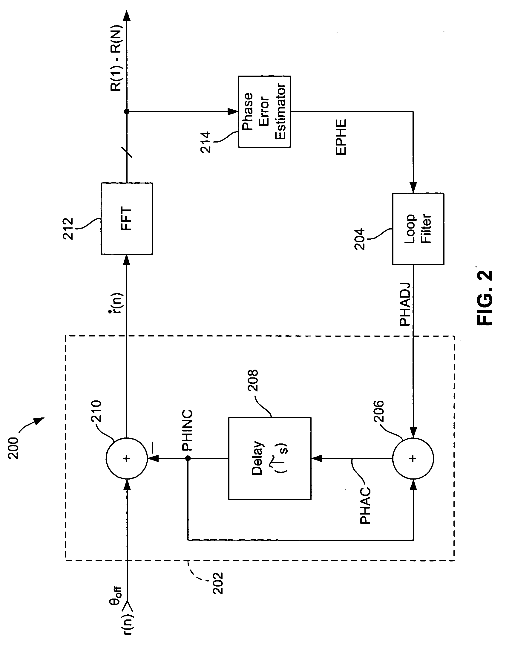
[0021] According to one aspect of the present invention, a carrier tracking circuit includes a first phase adjustment circuit coupled to an input of a delay element and a second phase adjustment circuit coupled to an output of the delay element. A phase correction circuit is coupled to output of the delay element is operable to generate a phase adjustment value based upon a data symbol output from the delay element. The phase correction circuit includes a double phase correction circuit to prevent double application of the same phase adjustment value to a symbol by both the first and second phase adjustment circuits. The carrier tracking circuit may be used in OFDM communications systems with each data symbol being an OFDM symbol and with the delay element being an FFT. The carrier tracker circuit also may include a feed forward circuit for correcting the phase error of a given data symbol using a phase error generated from that symbol.

Problems solved by technology

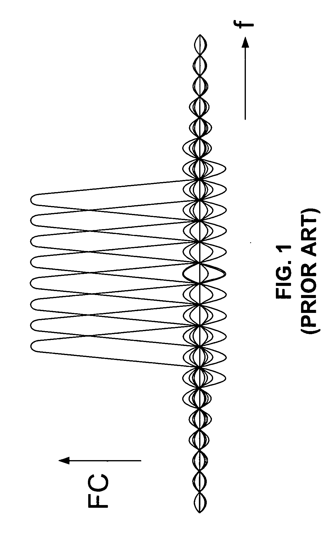
Although OFDM is well suited for use in wireless communications systems as previously mentioned, there are nonetheless types of distortion that must be compensated for with OFDM just as with any modulation technique.
One such type of distortion is frequency-offset distortion that results from a difference between the frequency of an oscillator or RF signal generated by the local oscillator in the OFDM transmitter and the frequency of the RF signal generated by the local oscillator in the OFDM receiver.
Such a frequency offset results in the OFDM signal having a frequency offset relative the original OFDM signal in the transmitter, and this type of distortion can adversely affect the performance of the system.
Such a frequency offset results in a linearly cumulative phase error for each sample r(n) of the OFDM signal, as will be understood by those skilled in the art.
This may result in inaccurate phase adjustments of the samples r(n) in the subsequent OFDM symbol due to the intervening linearly cumulative phase error of the samples.

Method used


Image

  • Carrier tracking circuit and method including dual numerically controlled oscillators and feedforward phase correction coefficient
  • Carrier tracking circuit and method including dual numerically controlled oscillators and feedforward phase correction coefficient
  • Carrier tracking circuit and method including dual numerically controlled oscillators and feedforward phase correction coefficient

Examples


Embodiment Construction

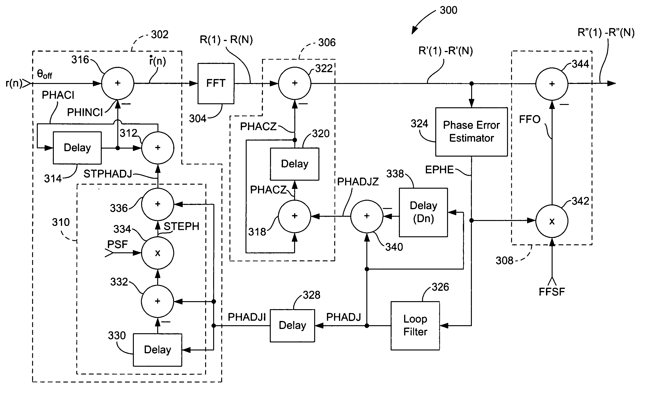
[0027]FIG. 3 is a functional block diagram of a carrier tracking circuit 300 including a first numerically controlled oscillator (NCO) 302 for adjusting the phase of the samples r(n) of an OFDM symbol prior to those samples being input to an FFT 304. The carrier tracking circuit 300 further includes a second NCO 306 for quickly adjusting the phases of the frequency components R(1)-R(64) that are output by the FFT 304 for an OFDM symbol using an estimated phase error EPHE for the immediately preceding OFDM symbol. Moreover, the carrier tracking circuit 300 also includes a feed forward phase correction circuit 308 for immediately adjusting the phase errors of the frequency components R(1)-R(64) of a given OFDM symbol using a scaled estimate of the phase error EPHE for that symbol. The NCO 302 further includes an intrasymbol step phase compensation circuit 310 that generates a step increment in the phase adjustment applied to the samples r(n) by the NCO 302 to compensate for the additi...


PUM


Abstract

A carrier tracking circuit includes a first phase adjustment circuit coupled to an input of a delay element and a second phase adjustment circuit coupled to an output of the delay element. A phase correction circuit is coupled to output of the delay element is operable to generate a phase adjustment value based upon a data symbol output from the delay element. The phase correction circuit includes a double phase correction circuit to prevent double application of the same phase adjustment value to a symbol by both the first and second phase adjustment circuits. The carrier tracking circuit may be used in OFDM communications systems with each data symbol being an OFDM symbol and with the delay element being an FFT. The carrier tracker circuit also may include a feed forward circuit for correcting the phase error of a given data symbol using a phase error generated from that symbol.

Description

PRIORITY CLAIM [0001] This application claims priority from U.S. Provisional Patent Application No. 60 / 449,042 filed Feb. 21, 2003, which is incorporated herein by reference.TECHNICAL FIELD [0002] The present invention relates generally to communications systems and more specifically to the correction of frequency offsets between receivers and transmitters in such communications systems. BACKGROUND OF THE INVENTION [0003] In a typical communications system, a transmitter encodes data to be transmitted and this encoded data is used to modulate a carrier signal which is transmitted over a communications channel to a receiver. The receiver demodulates the received carrier signal to obtain the encoded data and thereafter decodes the encoded data to obtain the original data sent by the transmitter. The type of modulation utilized in the communications system indicates the parameter of the carrier signal that is varied to encode the data onto the carrier signal, such as amplitude, frequen...

Claims


Application Information

Patent Timeline
IPC IPC(8): H04L27/22
CPCH04L27/2657H04L2027/0032H04L2027/0046H04L2027/0055
Inventor MACFARLANE SHEARER, DANIEL DAVIDSON IIISEALS, MICHAEL J.
Owner INTELLECTUAL VENTURES I LLC
Learn More