
Light fixture lens retaining device and method

a technology for retaining devices and lighting fixtures, applied in the field of lens retaining devices and methods, can solve the problems of lens damage, heavy foot traffic, rain, dirt, etc., and achieve the effect of avoiding waste and expense of replacing the bezel, and enhancing the flexibility of lens and lighting characteristics

Active Publication Date: 2006-06-22
TORO CO THE
View PDF3 Cites 14 Cited by
  • Summary
  • Abstract
  • Description
  • Claims
  • Application Information

AI Technical Summary

Benefits of technology

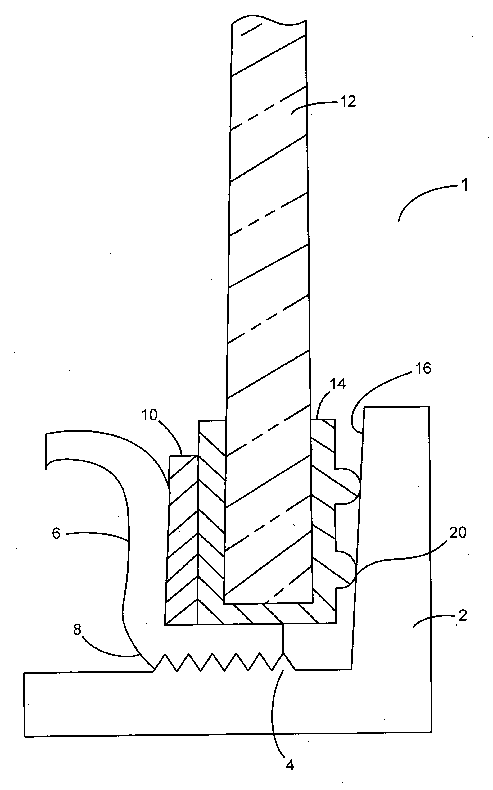
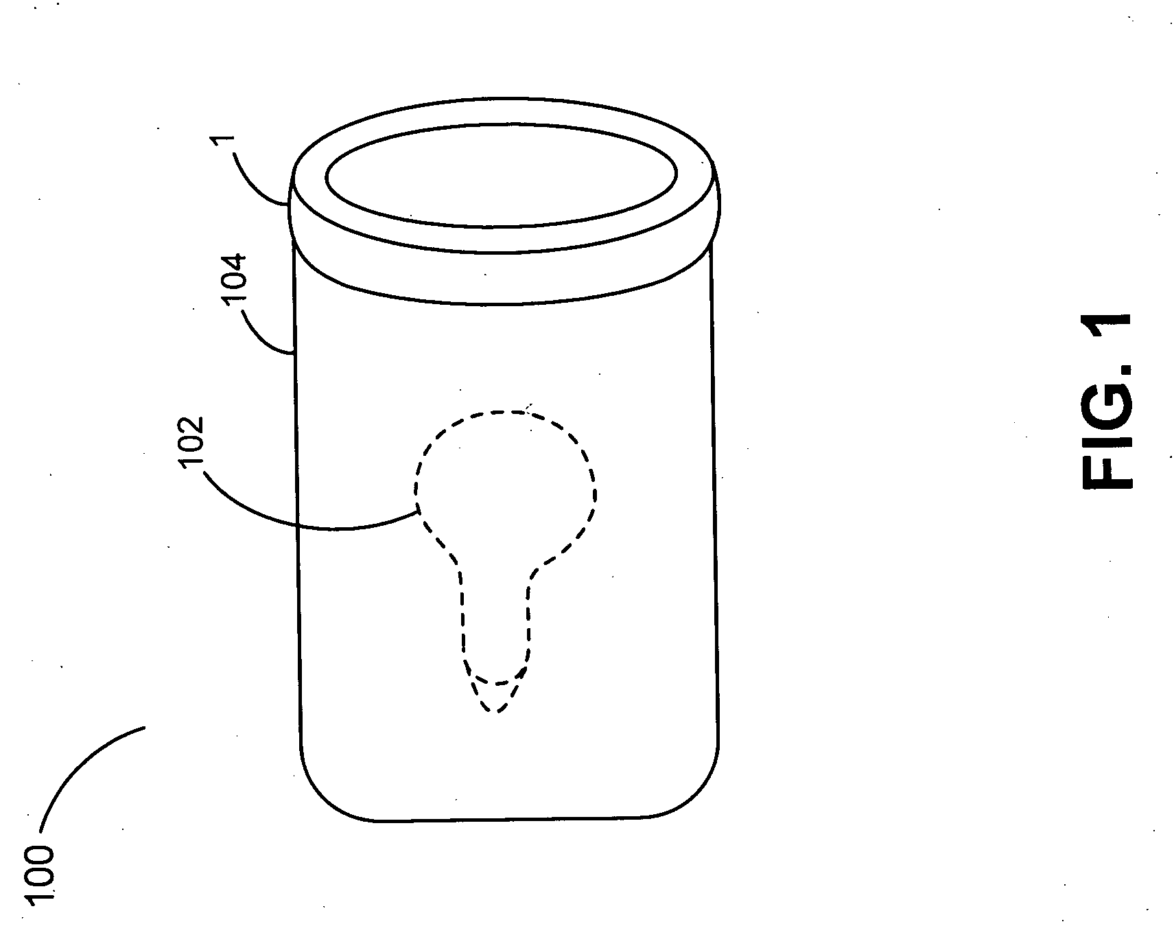
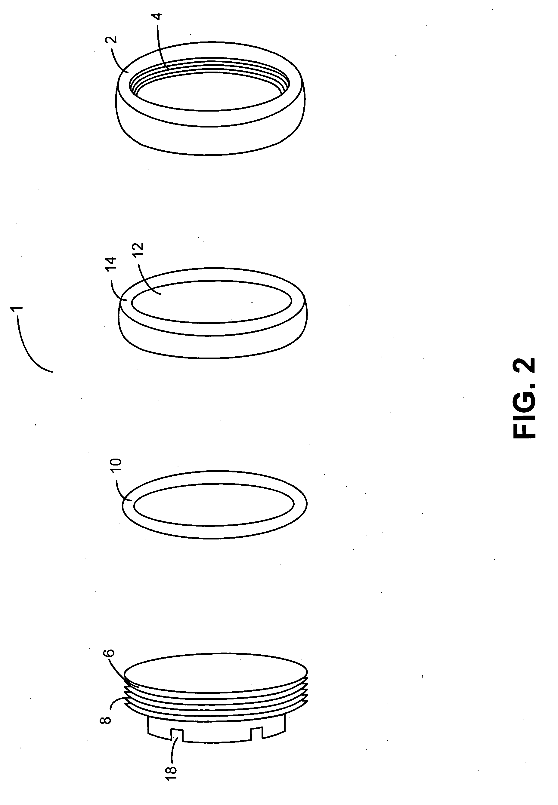
The present invention provides a convenient way to replace and retain lenses in lighting fixtures. It includes a bezel for housing the lens and a removable lens retainer and contact ring for easy replacement of lenses. The bezel has threads, and a retaining ring with external features engages the threads to press the lens and seal into contact with the bezel. The retaining ring and bezel combination can accommodate lenses of varying thicknesses. The invention avoids the waste and expense of replacing an entire light because of a broken lens or seal, and provides flexibility in lens and lighting characteristics.

Problems solved by technology

Outdoor lighting fixtures are typically subjected to rain, dirt, sprinklers, and general weathering by the elements.
In addition, lighting fixture lenses mounted at or near ground level may be further subjected to impact, pressure, abrasion and possibly pooling of water.
For example, lighting fixtures mounted flush with the ground in an area of heavy foot or automobile traffic are more prone to lens damage.
Glues and epoxies often fail as a result of the different thermal expansion properties of the bezel, lens, and glue or epoxy.
Failure of such glues, breakage of a lens, or compromise of a lens seal typically calls for replacement of the costly bezel-lens combination or of the entire light.
Lens bezels are typically ornamental and are, therefore, relatively expensive compared to the lens or seal components.
Attempted reuse of a bezel with a broken glued-in lens is problematic, where the old lens and glue must be removed before adhesion of the replacement lens to ensure proper sealing and aesthetics.
The useable life of prior lighting systems is too often limited either functionally or financially by the limited durability of lenses that are not independently or easily replaceable.

Method used


Image

  • Light fixture lens retaining device and method
  • Light fixture lens retaining device and method
  • Light fixture lens retaining device and method

Examples


Embodiment Construction

[0018] The following description is of exemplary embodiments of the invention only, and is not intended to limit the scope, applicability, or configuration of the invention in any way. While exemplary embodiments are described in sufficient detail to disclose the best mode and to enable those skilled in the art to practice the invention, it should be understood that other embodiments may be realized and that various mechanical changes may be made without departing from the scope of the invention as set forth herein. It should be appreciated that the description herein may likewise be adapted to be employed with alternatively configured devices having different shapes, components, and the like and still fall within the scope of the present invention. Thus, the detailed description herein is presented for purposes of illustration only and not of limitation.

[0019] According to various exemplary embodiments of the present invention, a lens and lens seal are independently replaceable wi...


PUM


Abstract

The present invention provides a retainer assembly and method for securely retaining a lens in a housing such as a light fixture bezel. An exemplary retainer assembly includes a lens and lens seal within a light bezel having threads and a contact surface formed on the bezel interior, a retaining ring having external features for engaging the threads on the bezel interior, and a contact ring disposed between the retaining ring and the lens to be secured in the bezel. An exemplary method involves the steps of placing a seal around the periphery and edge of a disc shaped lens, seating the lens within the lens bezel or retaining ring, and advancing the retaining ring within the bezel with a contact ring adjacent the lens and seal to prevent wear from rotation.

Description

REFERENCE TO RELATED APPLICATION [0001] The present application claims the benefit of U.S. provisional application Ser. No. 60 / 593,198, filed Dec. 20, 2004.FIELD OF INVENTION [0002] The present invention pertains generally to lens retaining devices and methods and more particularly to devices and methods for removably securing and sealing lenses within a light fixture bezel. BACKGROUND OF THE INVENTION [0003] Outdoor lighting fixtures are typically subjected to rain, dirt, sprinklers, and general weathering by the elements. In addition, lighting fixture lenses mounted at or near ground level may be further subjected to impact, pressure, abrasion and possibly pooling of water. It is thus, important that lenses be durable, and that lenses be readily replaceable, since some lenses may inevitably fail under certain circumstance. For example, lighting fixtures mounted flush with the ground in an area of heavy foot or automobile traffic are more prone to lens damage. [0004] Prior art lens...

Claims


Application Information

Patent Timeline
Patent Type & Authority Applications(United States)
IPC IPC(8): G02B7/02
CPCG02B7/026
Inventor HILLE, JONATHAN D.
Owner TORO CO THE
Learn More