
Power converter

a power converter and converter technology, applied in the direction of electric variable regulation, process and machine control, instruments, etc., can solve the problem of system availability falling

Inactive Publication Date: 2006-06-22
MITSUBISHI ELECTRIC CORP
View PDF8 Cites 22 Cited by
  • Summary
  • Abstract
  • Description
  • Claims
  • Application Information

AI Technical Summary

Benefits of technology

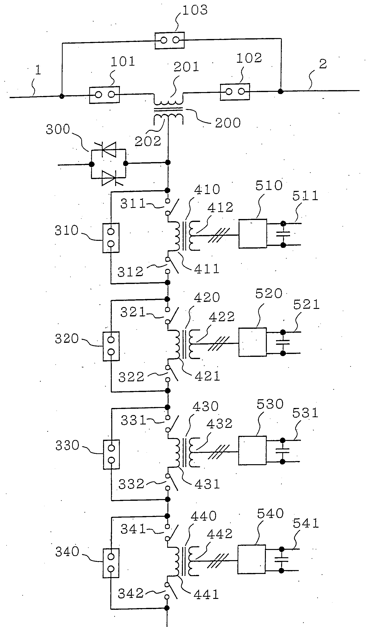
[0005] The invention provides a power converter having a series transformer with its primary winding connected in series with a line, multiple array transformers connected in series with the secondary winding of this series transformer, normally-on switches connected in series with the ends of the primary windings of the array transformers, normally-off current bypass devices connected in parallel with the series connections of the primary windings of the array transformers and the switches at their ends, AC-DC converter units having their AC sides connected to each of the secondary windings of the multiple array transformers, and mutually independent DC circuits severally connected to the DC sides of the AC-DC converter units, wherein by turning on the current bypass device of the primary winding of a specified array transformer and turning off the switches at the ends of that primary winding it is possible to isolate the specified array transformer and the AC-DC converter unit connected to it.
[0006] By this means it is possible not only to increase the availability and the reliability of the apparatus as a whole but also to raise the capacity of the apparatus by easily making additions to it.
[0007] The invention also provides a power converter including multiple array transformers having their primary windings connected to a line in series, normally-on switches connected in series with the ends of the primary windings of the array transformers, normally-off first current bypass devices connected in parallel with the series connections of the primary windings of the array transformers and the switches connected to their ends, AC-DC converter units having their AC sides connected to the secondary windings of each of the array transformers, mutually independent DC circuits connected to the DC sides of the AC-DC converter units, and a normally-off second current bypass device connected in parallel with all of the series-connected array transformers, wherein by turning on the first current bypass device of the primary winding of a specified array transformer and turning off the switches at the ends of that primary winding it is possible to isolate the specified array transformer and the AC-DC converter unit connected to it.
[0008] By this means it is possible not only to increase the availability and the reliability of the apparatus as a whole but also to raise the capacity of the apparatus by easily making additions to it.

Problems solved by technology

And there has been the problem that the power converter has to be shut down until repair or periodic checking is complete, and the availability of the system falls.

Method used


Image

  • Power converter
  • Power converter
  • Power converter

Examples


first preferred embodiment

[0017]FIG. 1 is a circuit diagram showing the construction of a first preferred embodiment of a power converter according to the invention. (Throughout the figures, the same reference numerals denote the same or equivalent parts and hereinafter referred to as the same meaning.) In FIG. 1, the primary winding 201 of a series transformer 200 is connected in series between a power supply side 1 of a line and a power supply side or load side 2 of the line. The primary windings 411 to 441 of array transformers 410 to 440 (the case of a four-stage array is shown) are connected in series to the secondary winding 202 of the series transformer 200. The AC sides of four AC-DC converter units 510 to 540 are respectively connected to the secondary windings 412 to 442 of the array transformers 410 to 440, and mutually independent DC circuits 511 to 541 are connected the DC sides of the AC-DC converter units 510 to 540.

[0018] This power converter according to the invention is of a construction s...

second preferred embodiment

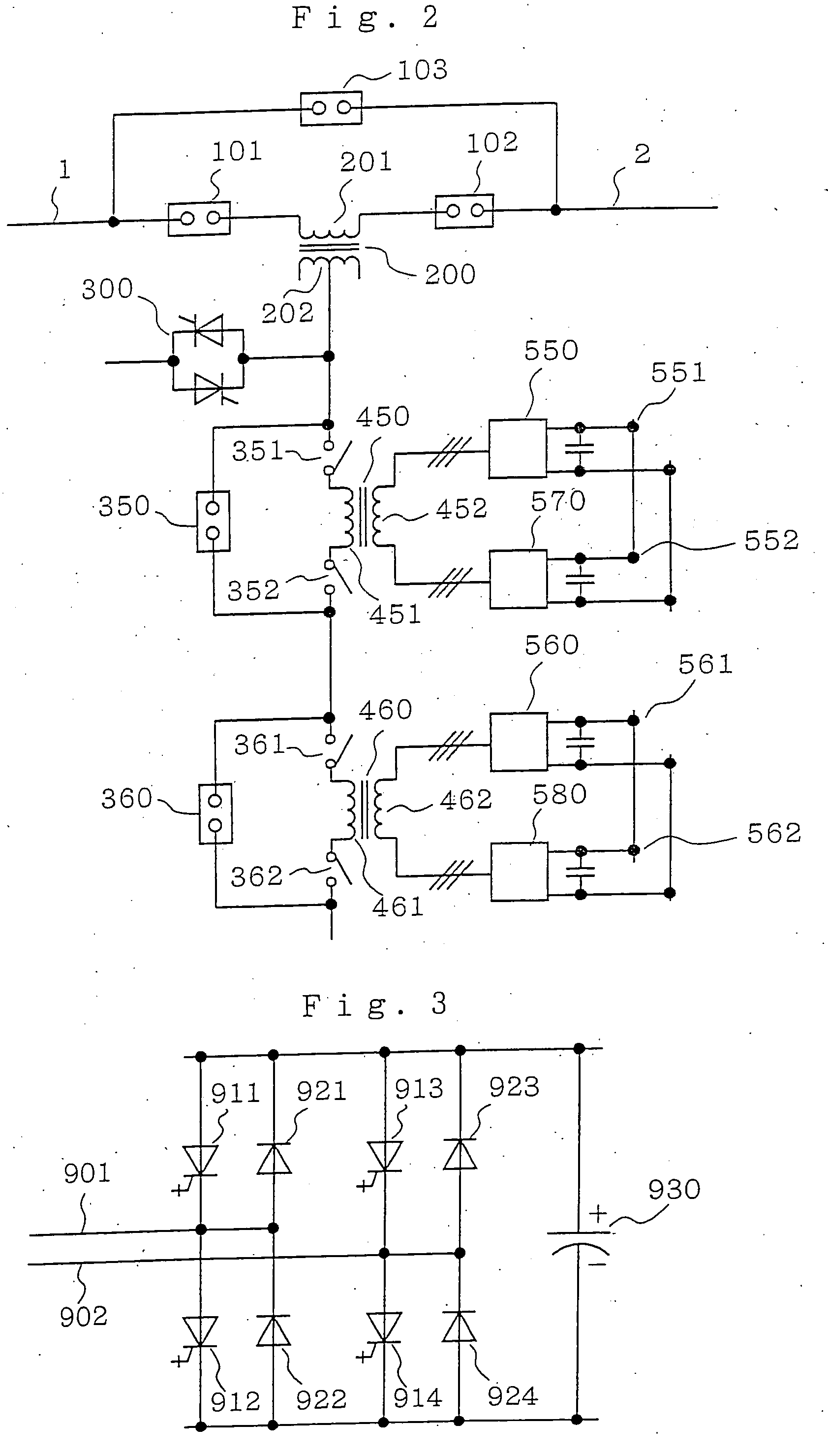
[0030] Whereas in the first preferred embodiment a construction was adopted such that the AC-DC converter units 510 to 540 could be isolated one at a time, as shown in FIG. 2, AC-DC converter units 550 to 580 are connected to the secondary windings 452 and 462 of array transformers 450 and 460 two by two. In this case, although the two DC circuits 551 and 552 forming one pair are common, they are independent from the DC circuits 561 and 562 forming another pair. This point is similar to the first preferred embodiment.

[0031] When the number of AC-DC converter units is 2×N, compared to the first preferred embodiment, because the number of array transformer stages is N, i.e. half the number in the first preferred embodiment, the manufacturing cost of the array transformers can be expected to be cheaper. In this second preferred embodiment the AC-DC converter units have to be shut down in twos when there is a failure of an AC-DC converter unit or for a periodic check, but if redundancy...

third preferred embodiment

[0033] Whereas in the first preferred embodiment a series transformer 200 was disposed between a power supply side 1 of a line and a power supply side or load side 2 of the line and array transformers 410 to 440 and AC-DC converter units 510 to 540 were provided, the array transformers 410 to 440 can also be connected in series between a power supply side 1 of a line and a power supply side or load side 2 of the line directly, as in a third preferred embodiment shown in FIG. 4. A current bypass device (circuit breaker, isolator or semiconductor switch) 300 is connected in parallel with all the primary windings 411 to 441 of the array transformers 410 to 440, and at the time of a line accident bypasses all of the primary windings 411 to 441 of the array transformers 410 to 440 together.

[0034] The circuit in FIG. 4 can be applied in cases such as when the array transformers can be connected to the line directly, when semiconductor switches can be connected to the line directly, and w...


PUM


Abstract

A power converter that can continue to operate after suffering a partial failure. The power converter includes multiple array transformers; normally-on switches connected respectively in series with the ends of each of the primary windings of the array transformers; normally-off current bypass devices connected in parallel with the series connections of the primary windings of the array transformers and the switches at the transformer ends; AC-DC converter units having AC sides respectively connected secondary windings of the array transformers; and mutually independent DC circuits respectively connected to DC sides of the AC-DC converter units. By turning on the current bypass device of the primary winding of a specified array transformer and turning off the switches at the ends of that primary winding it is possible to isolate the specified array transformer and the AC-DC converter unit connected to it.

Description

TECHNICAL FIELD [0001] This invention relates to a power converter connected in series with a line such as a power line, a distribution line or a single-phase AC wire, and particularly to a power converter capable of continuing to operate after suffering a partial failure. BACKGROUND ART [0002]FIG. 8 is a circuit diagram showing the construction of a power converter of related art disclosed in for example U.S. Pat. No. 5,646,511. In this power converter, a series transformer having its primary winding connected in series with a power line, a distribution line or a single-phase AC wire for an electric train or the like (hereinafter abbreviated to ‘line’) and multiple array transformers on the secondary side of this series transformer are combined in two stages to connect AC-DC converter units to the line. This power converter has the function of a line power tide current control apparatus. In the figure, the primary winding 201 of a series transformer 200 is connected between the pow...

Claims


Application Information

Patent Timeline
IPC IPC(8): H02J3/00H02J1/10H02J3/12H02J3/18H02J5/00H02M5/10H02M7/08H02M7/483
CPCH02J3/1814H02J3/1857H02M1/32H02M5/10H02M5/44H02M7/483H02M2001/0074H02M2001/0077Y02E40/18Y02E40/26Y02E40/10Y02E40/20H02M1/0074H02M1/0077
Inventor ARITSUKA, TOMOHIKO
Owner MITSUBISHI ELECTRIC CORP
Learn More