
N-type schottky barrier tunnel transistor and manufacturing method thereof

a barrier tunnel transistor and manufacturing method technology, applied in the field of semiconductor devices, can solve the problems of deterioration of the operation characteristic affecting the efficiency of the semiconductor device, so as to improve the saturated current, reduce the parasitic resistance, and improve the effect of electrical conductivity

Inactive Publication Date: 2006-06-22
ELECTRONICS & TELECOMM RES INST
View PDF3 Cites 8 Cited by
  • Summary
  • Abstract
  • Description
  • Claims
  • Application Information

AI Technical Summary

Benefits of technology

[0009] The present invention provides an n-type SBTT of a source / drain structure and a manufacturing method thereof capable of reducing a parasitic resistance while introducing rare-earth metal silicide so as to form lower Schottky barrier.
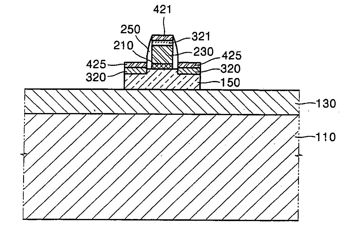
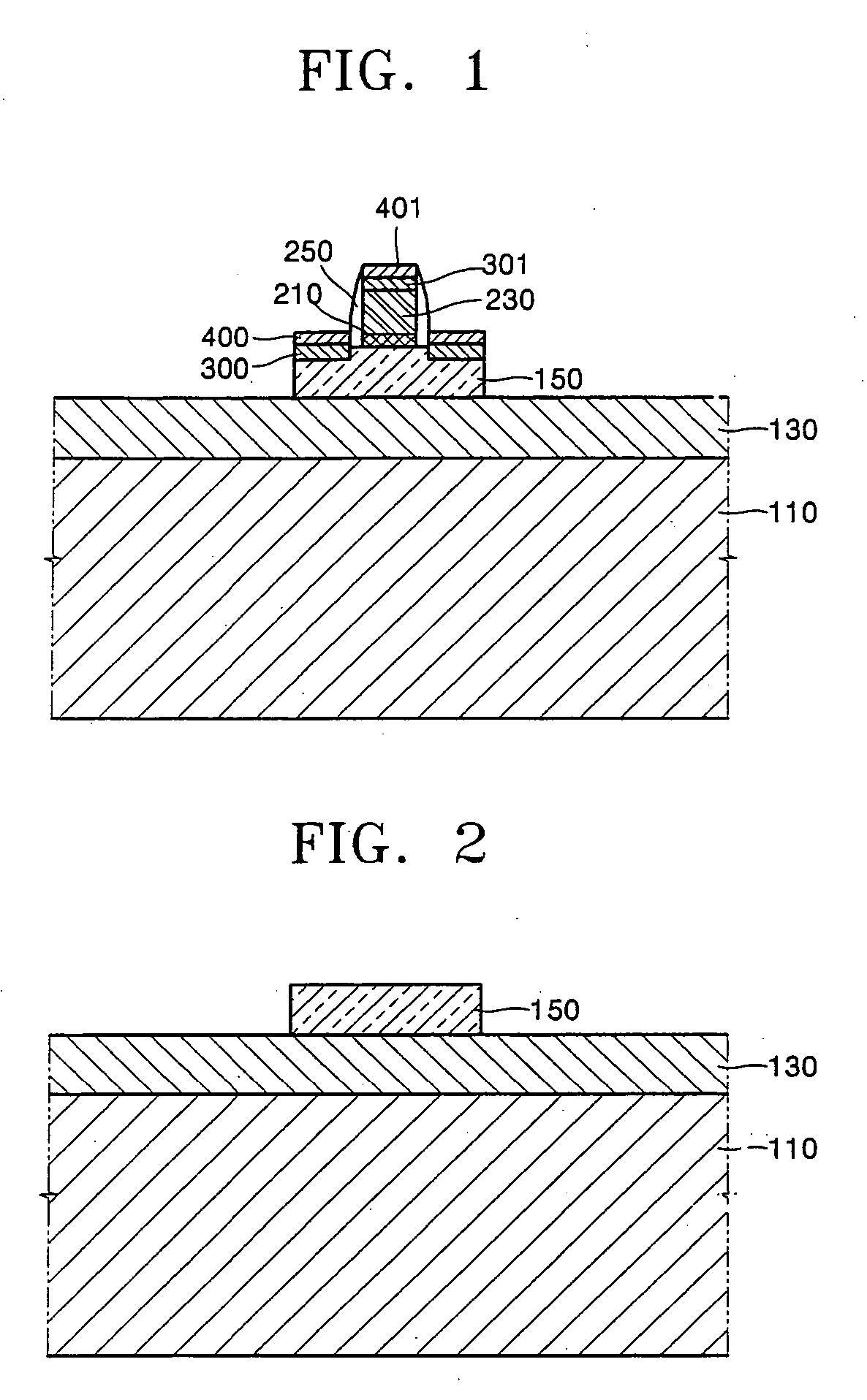
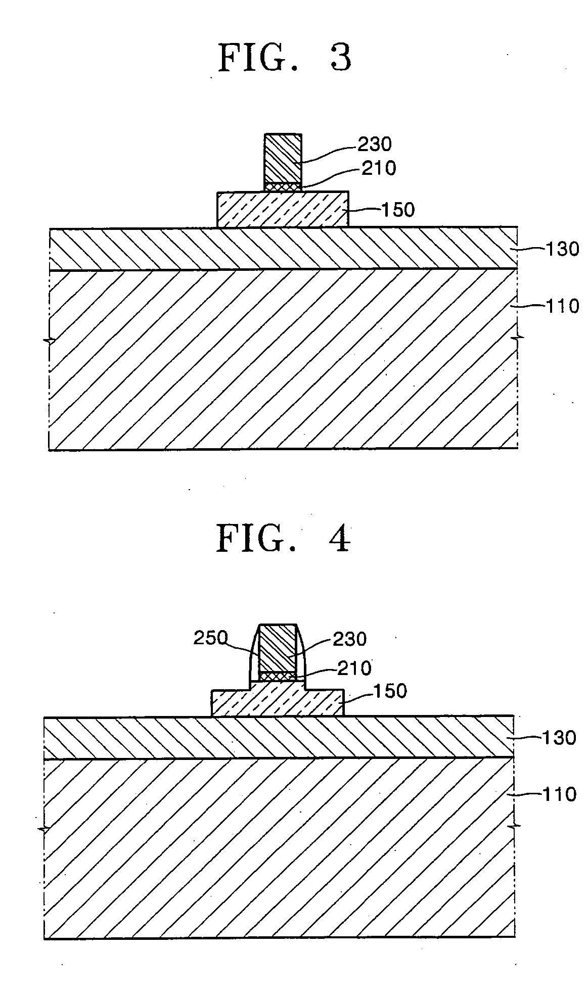
[0020] Further, an operation of forming a spacer on a sidewall of the gate before forming the rare-earth metal silicide layer can be further provided. An operation of having a step generated on the silicon layer portion where the source / drain is to be formed in a neighborhood of the spacer by performing a spacer etching for forming the spacer together with an over-etching can be further provided.
[0021] According to the present invention, it is possible to improve a saturated current by forming the transition metal silicide having very excellent electrical conductivity on the rare-earth metal silicide in order to reduce a parasitic resistance of the rare-earth metal silicide that forms a small Schottky barrier but has a large electric resistance.

Problems solved by technology

As a semiconductor device is microminiaturized in its size, a leakage current due to a short channel effect is remarkably increased and an operation characteristic of the semiconductor device is deteriorated.
Nevertheless, the rare-earth metal silicide may show a very weak thermal stability but shows a large electric specific resistance and thus is examined as having a small saturated current substantially.
Nevertheless, when forming the source and the drain with the rare-earth metal silicide of the single layer, an electric resistance is relatively large, whereby a larger saturated current cannot be obtained.

Method used


Image

  • N-type schottky barrier tunnel transistor and manufacturing method thereof
  • N-type schottky barrier tunnel transistor and manufacturing method thereof
  • N-type schottky barrier tunnel transistor and manufacturing method thereof

Examples


Embodiment Construction

[0026] The present invention will now be described more fully with reference to the accompanying drawings, in which exemplary embodiments of the invention are shown. The invention may, however, be embodied in many different forms and should not be construed as being limited to the embodiments set forth herein; rather, these embodiments are provided so that this disclosure will be thorough and complete, and will fully convey the concept of the invention to those skilled in the art. In the drawings, the thicknesses of layers and regions are exaggerated for clarity.

[0027] The embodiment of the present invention suggests a method for forming a silicide of a two-story structure without an undesired increase of the Schottky barrier capable of improving an operation characteristic of the SBTT by reducing a parasitic resistance of a source and a drain in an n-type SBTT manufactured by replacing the source and the drain with rare-earth metal silicide. Introduction of the rare-earth metal si...


PUM

PropertyMeasurementUnit
temperatureaaaaaaaaaa
sizeaaaaaaaaaa

Abstract

An n-type SBTT and a manufacturing method thereof are provided. The SBTT includes a silicon layer, a gate, a double layer that has a rare-earth metal suicide layer and a transition metal silicide layer. The silicon layer has a channel region. The gate is formed in an overlapping manner on the channel region and has a gate dielectric layer on its interface with respect to the silicon layer. The double layer is formed as a source / drain that has the channel region interposed on the silicon layer.

Description

CROSS-REFERENCE TO RELATED PATENT APPLICATION [0001] This application claims the benefit of Korean Patent Application No. 10-2004-0109298, filed on Dec. 21, 2004, in the Korean Intellectual Property Office, the disclosure of which is incorporated herein in its entirety by reference. BACKGROUND OF THE INVENTION [0002] 1. Field of the Invention [0003] The present invention relates to a semiconductor device, and more particularly, to an n-type Schottky barrier tunnel transistor (SBTT) and a manufacturing method thereof. [0004] 2. Description of the Related Art [0005] As a semiconductor device is microminiaturized in its size, a leakage current due to a short channel effect is remarkably increased and an operation characteristic of the semiconductor device is deteriorated. To overcome these problems, lots of researches are under progress. For one of examples, an SBTT may be suggested. [0006] The SBTT may be recognized as a device having a possibility of solving a problem caused by a sha...

Claims


Application Information

Patent Timeline
Patent Type & Authority Applications(United States)
IPC IPC(8): H01L29/76
CPCH01L21/2252H01L21/2254H01L21/28518H01L21/28537H01L29/458H01L29/4908H01L29/665H01L29/66636H01L29/7834H01L29/7839H01L21/18
Inventor KIM, YARK YEONJANG, MOON GYUSHIN, JAE HEONLEE, SEONG JAE
Owner ELECTRONICS & TELECOMM RES INST
Learn More