
Apparatus and method for testing the performance of a vehicle

a technology for vehicle performance and apparatus, applied in the direction of engine testing, structural/machine measurement, instruments, etc., can solve the problems of not providing all the information of interest to a buyer, the stand in use today does not comply, and the fault detection of an individual wheel is difficul

Inactive Publication Date: 2006-06-22
BEN DAVID YONA
View PDF4 Cites 28 Cited by
  • Summary
  • Abstract
  • Description
  • Claims
  • Application Information

AI Technical Summary

Benefits of technology

[0021] The utility of the present invention is further enhanced by the possibility of adding further optional equipment such as flywheels (for testing large vehicles) and a power absorption unit (for applying a steady-state load for extensive engine, retarder and gearbox testing).
[0022] Most prior-art vehicle test stands are equipped with encoders providing 100 pulses per revolution. By using a 1000 pulse encoder, preferably 1200, accuracy is much improved, the finer resolution being needed particularly for calculation of accelerations and decelerations, and for testing gear slip in automatic gearboxes.

Problems solved by technology

Most test stands in use today do not comply with these European standards Furthermore, as ABS systems have come into wider use, a need has arisen to test such braking systems under realistic conditions.
Prior art test stands may meet the requirements of the licensing authority but still do not provide all the information which is of interest to a buyer.
A further significant limitation of existing test stands is that the twin rollers which support the front or rear wheels are made long enough to cover the vehicle width.
This makes fault detection of an individual wheel difficult, and does not allow the testing of ABS braking systems.
Furthermore, prior art test stands have no arrangement for verifying the accuracy of the test apparatus.
A further limitation of present-day test stands is an inability to test the vehicle automatic transmission, without dismantling same, and without driving the vehicle out of the testing station.

Method used


Image

  • Apparatus and method for testing the performance of a vehicle
  • Apparatus and method for testing the performance of a vehicle
  • Apparatus and method for testing the performance of a vehicle

Examples


Embodiment Construction

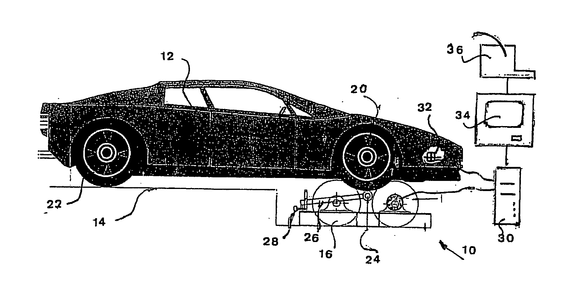
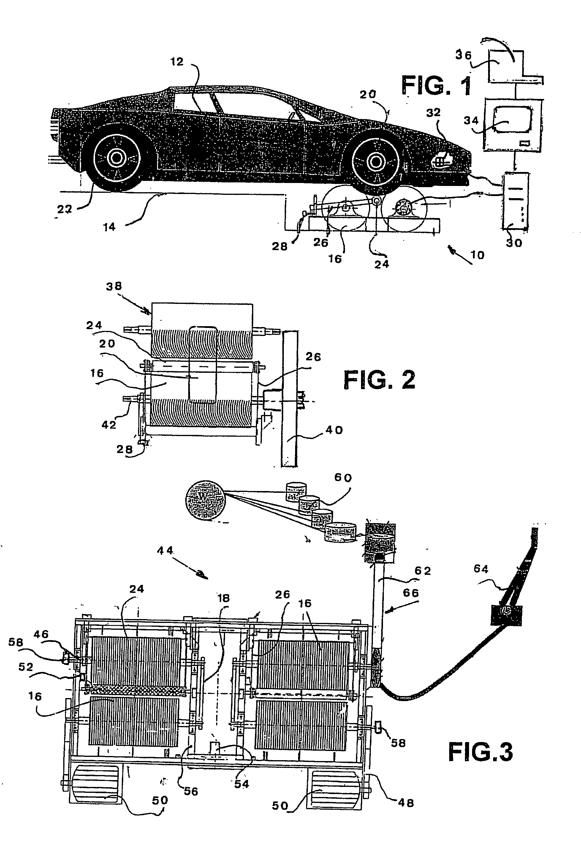
[0034] There is seen in FIG. 1 an apparatus 10 for testing the brakes, wheel alignment, suspension, transmission, and engine of motorized wheeled road vehicles. Means for calibrating the apparatus is included, and will be described with reference to FIGS. 3 & 11.

[0035] The figure shows a stationary light vehicle 12 partially resting on a platform 14. The platform is made strong and large enough to allow a heavy vehicle to be placed thereon.

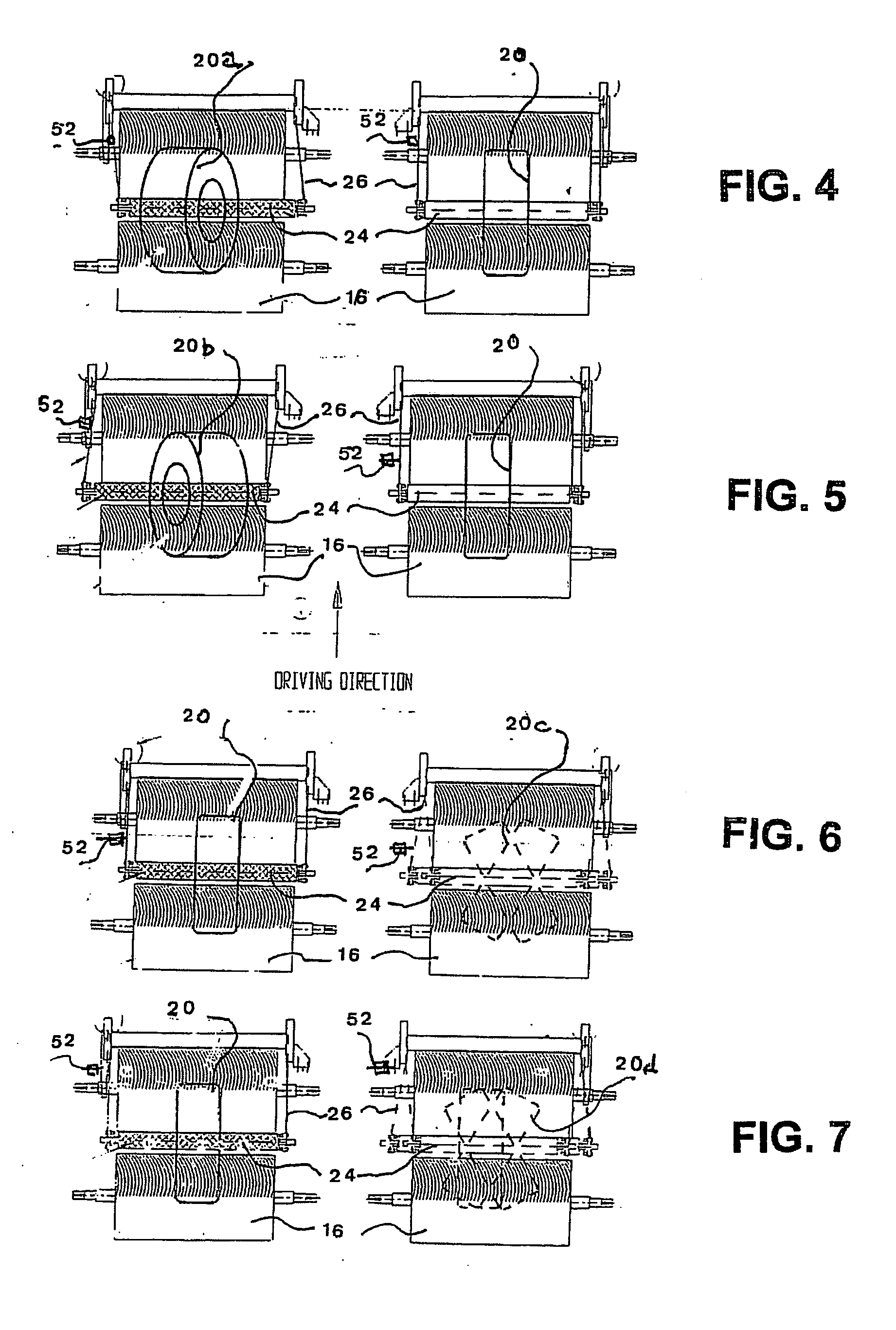
[0036] Two pairs of short, but high-inertia rollers 16 (seen to better effect in FIG. 3) are revolvably supported in a fixed relationship to the platform 14. Each pair of rollers 16 is interconnected by a chain drive 18, seen in FIG. 3, which is suitable as all rollers rotate in the same direction.

[0037] Advantageously, the high-inertia rollers 16 are grooved and are at least 400 mm diameter, larger than prior art rollers. The rollers are positioned to support either the front wheels 20, as seen in the figure, or the back wheels 22 of the vehic...


PUM

PropertyMeasurementUnit
diameteraaaaaaaaaa
diameteraaaaaaaaaa
diameteraaaaaaaaaa

Abstract

An apparatus for testing the brakes, wheel alignment, suspension, transmission, and engine of motorized wheeled vehicles, includes means such as a dynamometer for self-calibration. A platform supports a road vehicle to be tested. Two or four pairs of short high-inertia rollers are revolvably supported adjacent to said platform, and positioned to individually support either the front wheels or the back wheels of the vehicle. The rollers are drivable by a stationary vehicle resting thereon, each pair of high-inertia rollers supporting one vehicle wheel. A floating roller contacts the wheel to detect side forces. Sensor means are connected to the rollers and data processing, display and recording means are connected to the sensors. Speed of the rollers is monitored by an encoder having a resolution of at least 1000 pulses / sec. A preferred embodiment of the apparatus includes electric motors which can be connected to drive the rollers.

Description

CROSS REFERENCE TO RELATED APPLICATIONS [0001] This application claims the benefit of U.S. Ser. No. 10 / 185,751, filed on Jul. 1, 2002 and entitled, “SYSTEM FOR TESTING VEHICLE ROAD DYNAMIC, SAFETY SYSTEMS AND CALIBRATION OF THE TESTER SYSTEM”.FIELD OF INVENTION [0002] The present invention relates to the testing of road vehicles. More particularly, the invention provides an improved apparatus for testing the brakes, wheel alignment, and further essential components of a wheeled road vehicle while one or two vehicle wheels revolve while the vehicle remains stationary on the test stand. BACKGROUND OF THE INVENTION [0003] In many countries wheeled road vehicles, such as cars, trucks, vans, buses, need to be tested usually yearly, before a road license is granted to the owner by the controlling authority. The required tests include factors such as wheel alignment, steering, and brake functioning, besides visual examination of components such as tires. [0004] In recent years the European...

Claims


Application Information

Patent Timeline
Patent Type & Authority Applications(United States)
IPC IPC(8): G01M19/00G01L5/28G01M99/00G01M17/007
CPCG01L5/282G01M17/0072G01M17/0074
Inventor BEN-DAVID, YONA
Owner BEN DAVID YONA
Learn More