
Cartridge box of pneumatic toy gun

a toy gun and cartridge box technology, applied in the field of cartridge boxes of pneumatic toy guns, can solve the problems of reducing the effective firing of gas and damage to the elements, and achieve the effect of improving the selection function and the present invention

Active Publication Date: 2012-04-17
HU SHIH CHE
View PDF1 Cites 19 Cited by
  • Summary
  • Abstract
  • Description
  • Claims
  • Application Information

AI Technical Summary

Benefits of technology

[0007]It will be appreciated that the present invention provides a control system, with which the movement of the air lock system could be stopped when there is no bullet, thereby the defects of the conventional pneumatic toy gun, such as when there is no bullet, the gas will still flow to cause the waste of gas and the damages to the elements, could be overcome. Besides, considering some users enjoy firing without bullets, the present invention also provides a system for the users to choose to fire without bullet or not, thereby the selectable functions of the present invention have been improved.
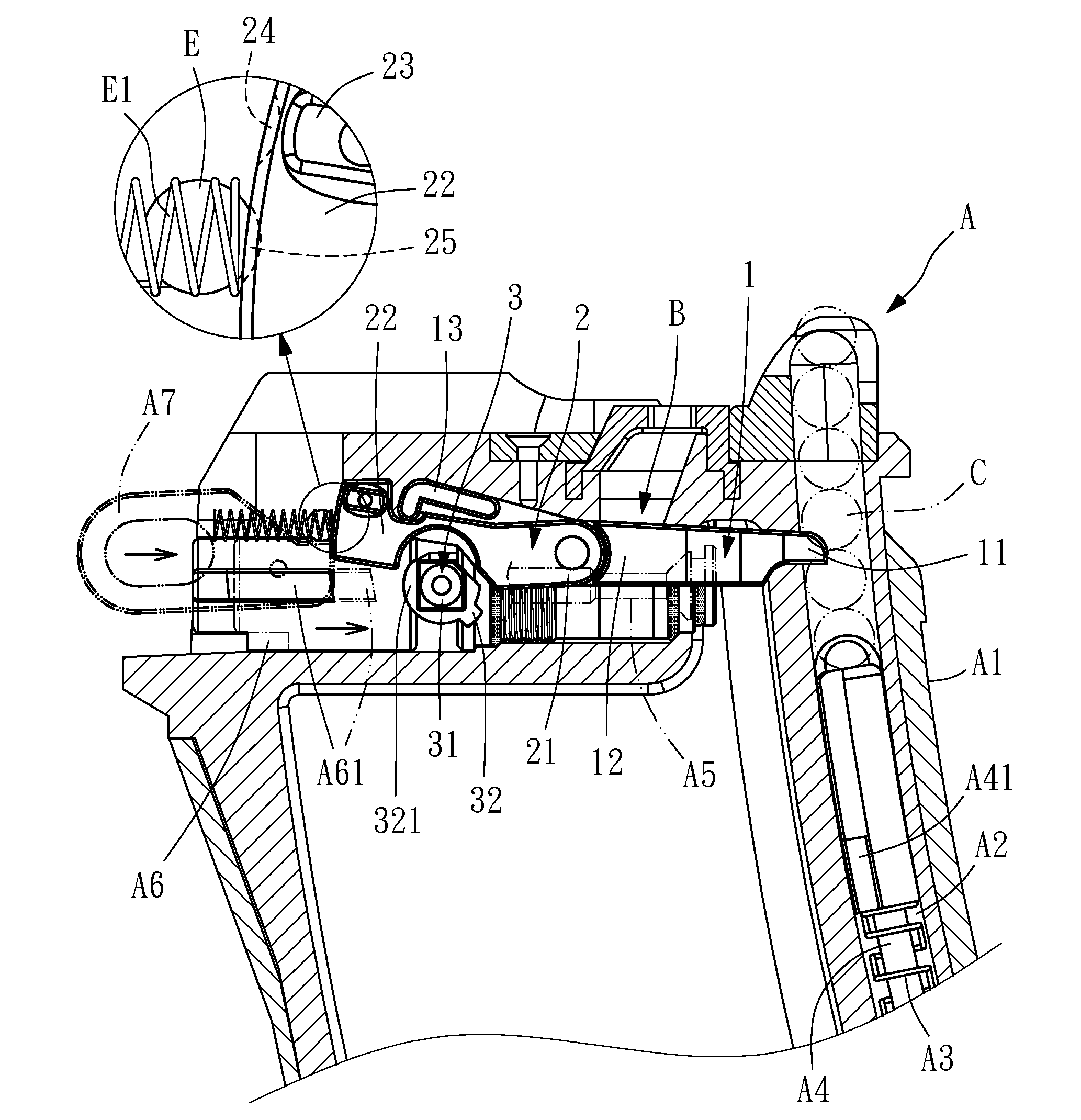
[0011]In addition, the resisting rod further has an upper locating portion and a lower locating portion, both of which are disposed on the back edge of the back end. A locating system is disposed in the case and behind the back end. The locating system has an elastic element disposed on the back to provide a forward elastic force to the locating system. Thereby, when the locking block of the back end of the resisting rod is moved to the first position, the locating system is elastically resisted against the lower locating portion of the resisting rod, and thus when the locking block of the back end of the resisting rod is moved to the second position, the locating system is resisted against the upper locating portion of the resisting rod. As a result, the locating will achieve.
[0013]Hence, the present invention provides a control system arranged to accomplish that, when there is no bullet in the pneumatic toy gun, the air lock system cannot be pushed forward and the bolt of the gun cannot move. Thereby, the momentum of the gas will not be wasted and the elements will not run idle to cause damages. Hence, the effects of the simulate gun can be achieved. Furthermore, the turning system is arranged for the users to choose to fire with or without bullets.

Problems solved by technology

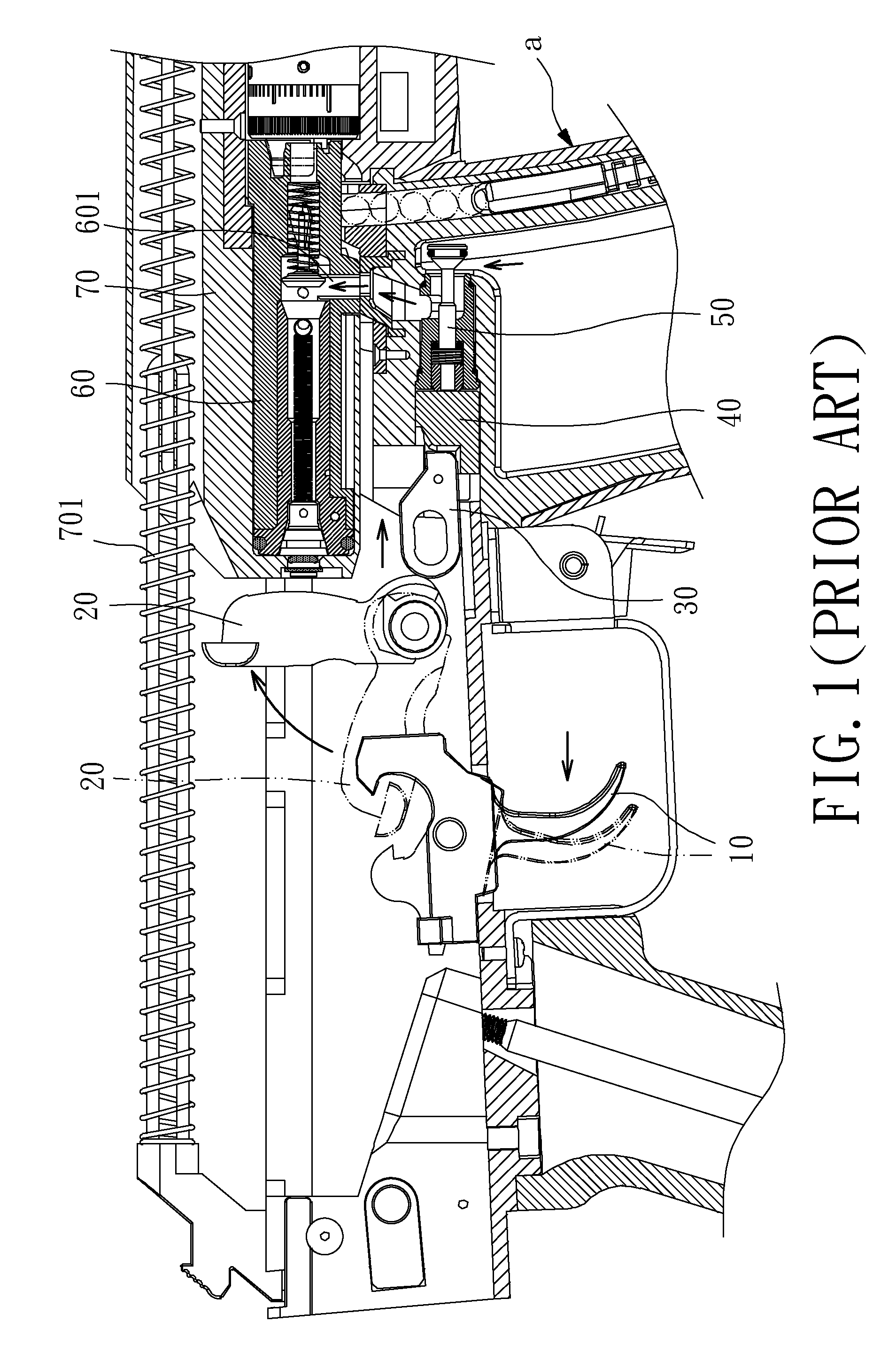
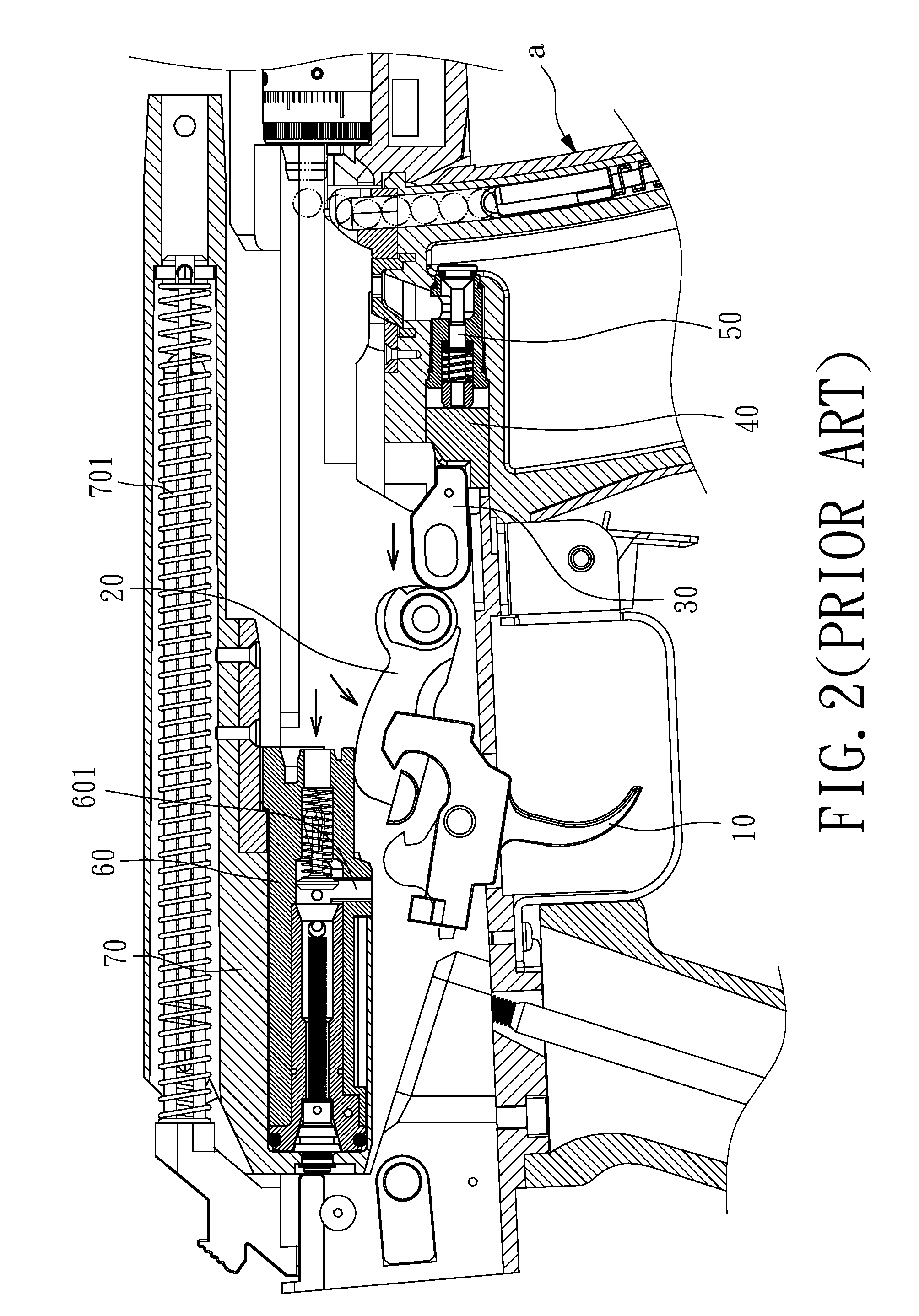
Hence, when there is no bullet, the continuous movements mentioned above make no sense, and also waste the gas in the cartridge box (a) and reduce the effective firing of the gas, both of which cause damages to the elements.

Method used


Image

  • Cartridge box of pneumatic toy gun
  • Cartridge box of pneumatic toy gun
  • Cartridge box of pneumatic toy gun

Examples


Embodiment Construction

[0025]Referring to FIG. 3, a cartridge box A of a pneumatic toy gun according to a preferred embodiment of the present invention is illustrated, which is capable of being used with an AK-type pneumatic toy gun, as well as the pneumatic toy guns showed in FIG. 1 and FIG. 2, wherein the operational principle of which will not be detailed described here. Instead, the cartridge box A will be introduced in detail.

[0026]Referring to FIG. 4, the cartridge box A comprises a case A1, a bullet-out passage A2 disposed on an inner side of the case A1, an elastic element A3 and a stripping rod A4, wherein both of the elastic element A3 and the stripping rod A4 are disposed inside the bullet-out passage A2. The elastic element A3 is disposed under the stripping rod A4 to provide an upwards elastic force to the stripping rod A4 which further has a lateral end A41.

[0027]Referring to FIG. 5, the case A1 further comprises an air lock system A5 and a struck element A6 on the upper inside, wherein the ...


PUM


Abstract

A cartridge box of a pneumatic toy gun includes an air lock system and a struck element disposed on the upper inside the case of the cartridge box, and further includes a control system having a pushing rod and a resisting rod, wherein a front end of the pushing rod extends into the bullet-out passage disposed inside the case. When there is no bullet in the bullet-out passage, a lateral end of the stripping rod resists upward against the front end of the pushing rod to make the back end of the resisting rod moving downward to resist against the resisting portion of the struck element, resulting that the struck element cannot push the air lock system forward. Thereby, when there is no bullet in the cartridge box, even if the trigger is pressed, the air lock system cannot moves to push the bolt. Hence, firing without bullet will be avoided and the effects of the simulate gun would be achieved. The cartridge box further has a turning system having a turning portion with a cam portion, which is turned upward to resist against the resisting rod, resulting that the resisting rod moves away from the resisting portion of the struck element. Thereby the bolt can be pushed to make a fire without bullet.

Description

BACKGROUND OF THE PRESENT INVENTION[0001]1. Field of Invention[0002]The present invention relates to a cartridge box of a pneumatic toy gun, and more particularly to a pneumatic toy gun, wherein when its trigger is pressed and its cartridge box contains no bullet, the bolt could be controlled by a user to be selectively moved forth and back.[0003]2. Description of Related Arts[0004]The driving principle of the pneumatic toy gun is different from that of the electrical toy gun. Referring to FIG. 1, when the trigger 10 of the pneumatic toy gun is pressed, the hammer 20 drives the firing pin 30 to move forth, which impact the struck element 40 disposed on the upper portion inside the cartridge box. Then the struck element 40 pushes the air lock system 50 forward to open the air inlet 601 of the plunger 60, thereby the inner gas of the cartridge box (a) flows into the plunger 60 to make the bolt 70 to move back as shown in FIG. 2. When the bolt 70 moves back, the hammer 20 is forced to ...

Claims


Application Information

Patent Timeline
Patent Type & Authority Patents(United States)
IPC IPC(8): F41A9/61F41B11/56F41B11/62
CPCF41A17/36F41B11/56F41B11/62
Inventor HU, SHIH-CHE
Owner HU SHIH CHE
Learn More