Compensated optical storage medium

a technology of optical storage media and which is applied in the field of compensating optical storage medium, can solve the problems of discs which cannot be read by, information storing institutions that cannot obtain the advantages of space saving media, and discs such as cd-roms tend to shatter, and achieve the effect of enduring high centrifugal forces

Inactive Publication Date: 2006-06-15
GLUD & MARSTRAND
View PDF8 Cites 5 Cited by
  • Summary
  • Abstract
  • Description
  • Claims
  • Application Information

AI Technical Summary

Benefits of technology

[0009] It is an object of the present invention to provide an optical storage medium capable of withstanding high centrifugal forces stemming from correspondingly high rotation speeds of the medium.
[0153] The nanostructure may represent an image and / or text, such as a hologram. The hologram may be used to provide a sign of the authenticity of the optical storage medium and thus show that the medium is not a copy. The different layers of the optical storage medium may comprise one or more holograms, this may provide a special visual effect as a resulting hologram may be obtained.

Problems solved by technology

A known property of plastic substrates is that the substrate deteriorate when exposed to UV light and thus over time the quality of the disc decrease resulting in a disc which can not be read by e.g. a compact disc player or a CD-ROM drive.
Due to the deteriorating nature of known optical storage media institutions storing information such as libraries, national archives etc. are reluctant to use the optical storage media.
Thus the information storing institutions fail to obtain the advantages of the space saving media.
However, present optical storage media are typically formed in a brittle polymeric material so that the disc, such as a CD-ROM tends to shatter when exposed to the induced centrifugal forces at these increased speeds.

Method used


Image

  • Compensated optical storage medium
  • Compensated optical storage medium
  • Compensated optical storage medium

Examples


Embodiment Construction

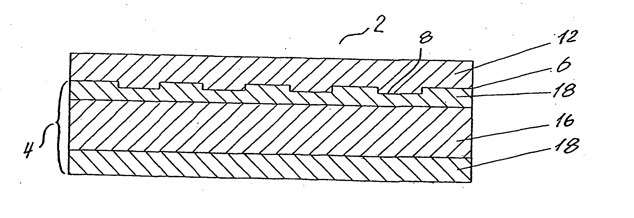
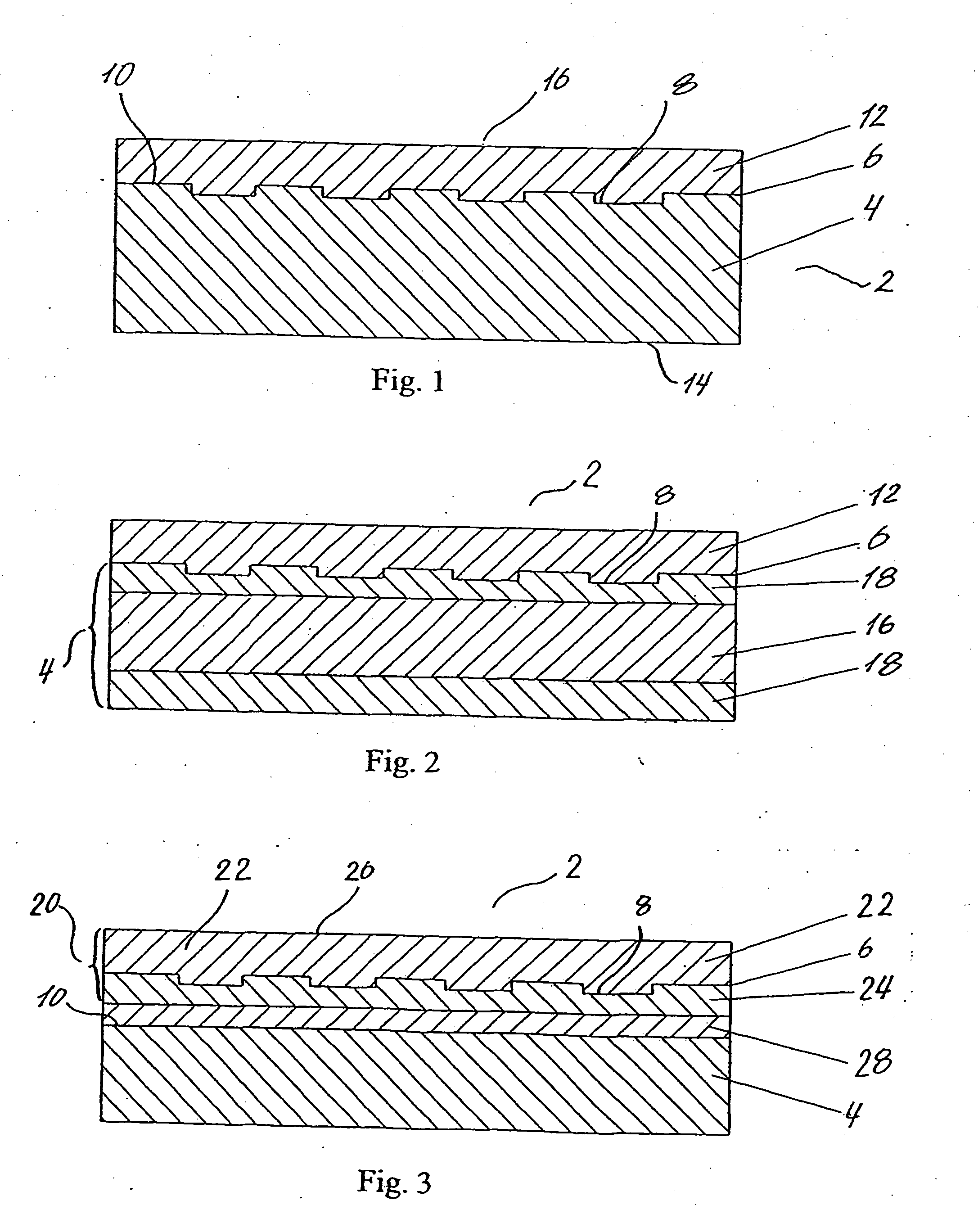
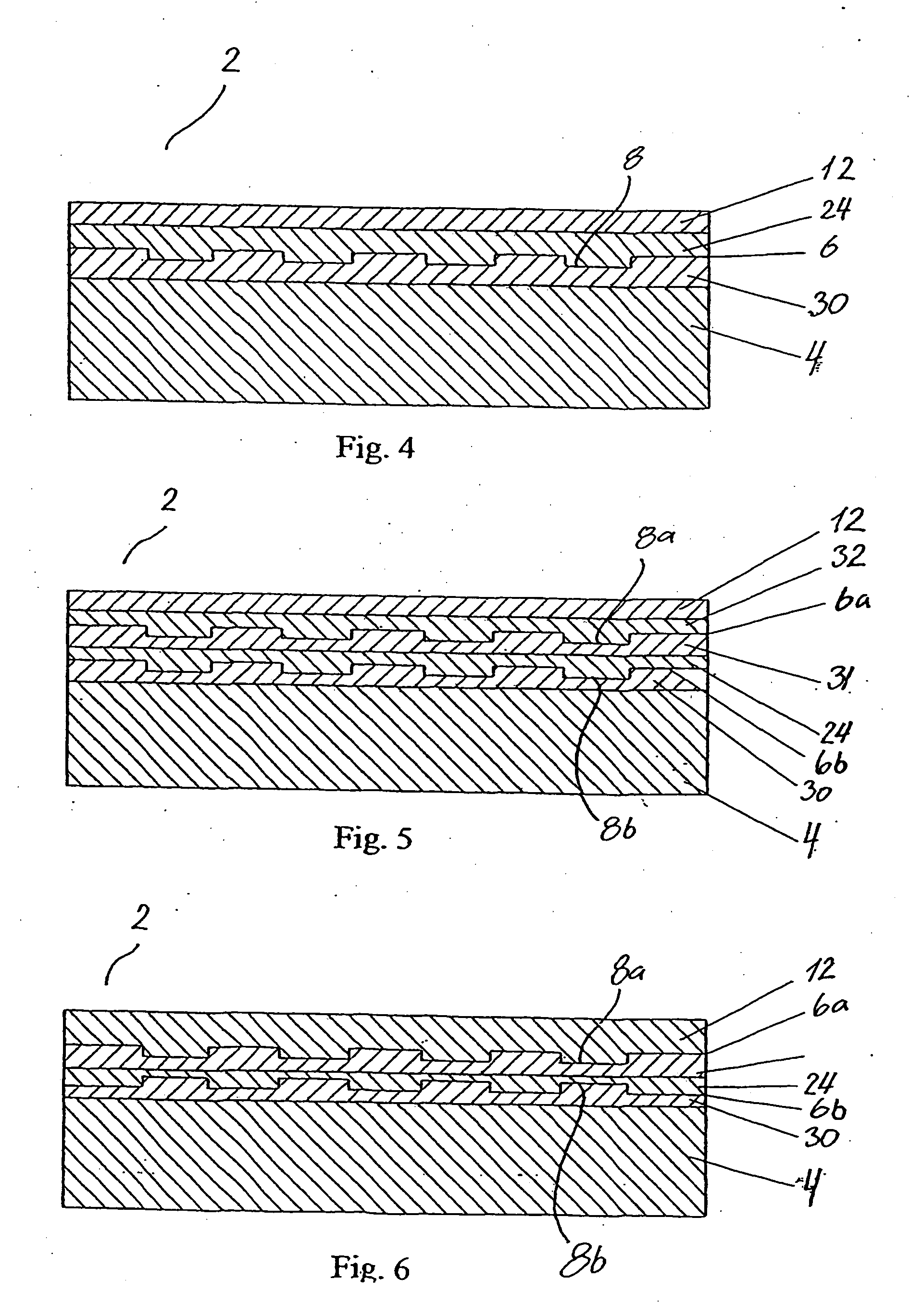
[0008] It is the object of the present invention to provide an optical storage medium which overcomes the above mentioned disadvantages.

[0009] It is an object of the present invention to provide an optical storage medium capable of withstanding high centrifugal forces stemming from correspondingly high rotation speeds of the medium.

[0010] It is a further object of the present invention to provide an optical storage medium which may be read by a standard optical playback device, such as any Compact Disc player, Digital Versatile Disc player, any PC or Mac comprising an optical disk drive, such as a DVD or CD-ROM drive, any game platform, such as Playstation®, Xbox®, Nintendo GameCube, any MP3 player, any MPEG player, etc.

[0011] It is a further object of the present invention to provide an optical storage medium which may be recorded in a standard optical recording device.

[0012] It is a further object of the present invention to provide an optical storage medium which comprises co...


PUM

PropertyMeasurementUnit
distanceaaaaaaaaaa
distanceaaaaaaaaaa
thicknessaaaaaaaaaa

Abstract

A optical storage medium is provided, comprising a main substrate, an information surface being associated with the main substrate, and at least one compensating layer. The compensating layer may change a phase and / or amplitude of a propagating electromagnetic wavefront according to a first optical transfer function so that the optical storage medium may be read or recorded by a detector / emitter being pre-set to read or record information at an information surface through a medium changing the phase and / or amplitude of a propagating wavefront according to a predetermined optical transfer function being different from the first optical transfer function. The compensating layer may optically reduce a spot size of a light beam incident on the information surface, and / or compensate for aberrations caused by a first distance being different from a predetermined distance. The substrate may be non-transparent and / or thinner than standard substrates. Methods of making such media are also provided.

Description

FIELD OF THE INVENTION [0001] The present invention relates to a compensated optical storage medium so as to allow the medium to be played in any play-back device, more particularly, the optical storage medium comprises a main substrate, an information surface being associated with the main substrate, and at least one compensating layer positioned between the information surface and an outer surface of the medium. Furthermore, the invention relates to a method for making said optical storage medium. BACKGROUND OF THE INVENTION [0002] Generally optical storage media are known. Examples of optical storage media are Compact Discs (CD) and Digital Versatile Discs (DVD). The media comprises a main substrate on which a nano-structure representing information in digital form is provided on a first surface of the disc. The digital information is read from a second opposite side of the disc and thus the main substrate is transparent. The transparent material is a plastic material often polyc...

Claims


Application Information

Patent Timeline
Patent Type & Authority Applications(United States)
IPC IPC(8): G11B7/24G11B7/013G11B7/2403G11B7/24047G11B7/24085G11B7/253G11B7/2531G11B7/2532G11B7/2533G11B7/2535G11B7/2536G11B7/2539G11B7/254G11B7/2542G11B7/258G11B7/2585G11B7/259G11B7/2595
CPCB82Y10/00G11B7/2403G11B7/24047G11B7/24085G11B7/252G11B7/253G11B7/2531G11B7/2532G11B7/2533G11B7/2535G11B7/2536G11B7/2539G11B7/2542G11B7/256G11B7/2585G11B7/259G11B7/2595G11B7/26
Inventor LINDVOLD, LARSTIDEMANN, JESPER
Owner GLUD & MARSTRAND
Why Eureka
Try Eureka