
LED light source

a technology of led light source and led light, which is applied in the direction of light source semiconductor devices, lighting and heating apparatus, instruments, etc., can solve the problems of unstable performance of cold cathode fluorescent lamps and dark regions of backlight modules, and achieve the effect of reducing the thickness of backlight modules, improving the thickness of conventional backlight modules, and increasing the cos

Active Publication Date: 2006-06-15
EPISTAR CORP
View PDF12 Cites 107 Cited by
  • Summary
  • Abstract
  • Description
  • Claims
  • Application Information

AI Technical Summary

Benefits of technology

The present invention provides a tube type LED light source with a more uniform brightness and a thinner backlight module for flat panel displays. The light source includes a light source generator, a light guide, and a diffuser with a grooved light incident surface and a grooved light-guiding surface. The cross-section of the grooved light incident surface is circular, elliptic, or polygonal. The diffuser may have a distributed pattern or a Moiré lens for mixing the incident light. The light source generates white light, which can be generated from a white light LED or by mixing lights of different colors. The light guide and diffuser are made of materials such as acrylic resin, COC, PMMA, PC, polyetherimide, fluorocarbon polymer, or silicone. The grooved light incident surface has a groove of strip type or concave openings. The use of the tube type LED light source in a backlight module reduces the need for a light guiding plate, simplifies the fabrication process, lowers cost, and makes the module thinner.

Problems solved by technology

Besides, the performance of the cold cathode fluorescent lamps is unstable and will cause the backlight module to have a dark region if any of the cold cathode fluorescent lamps is failed.

Method used


Image

  • LED light source
  • LED light source
  • LED light source

Examples


Embodiment Construction

[0041] Reference will now be made in detail to the present preferred embodiments of the invention, examples of which are illustrated in the accompanying drawings. Wherever possible, the same reference numbers are used in the drawings and the description to refer to the same or like parts.

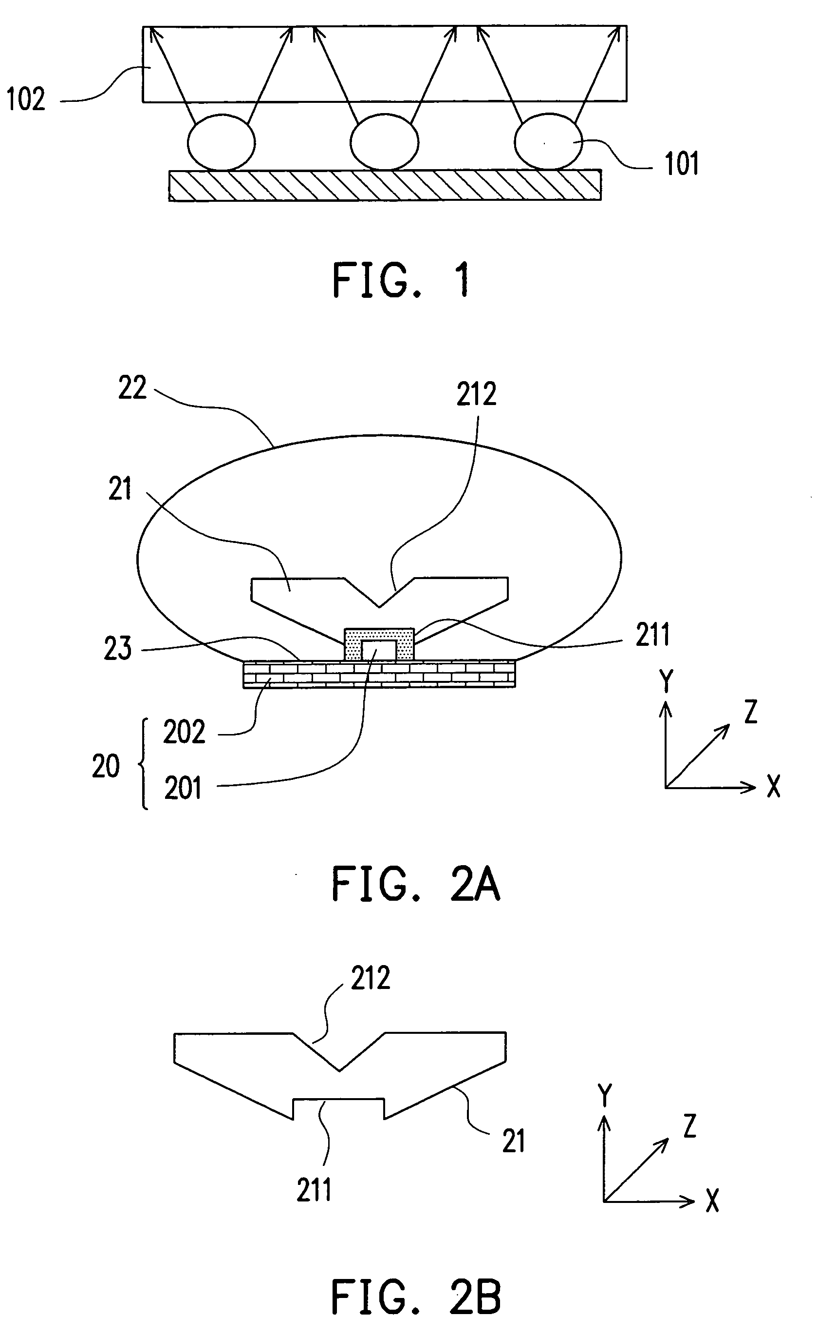
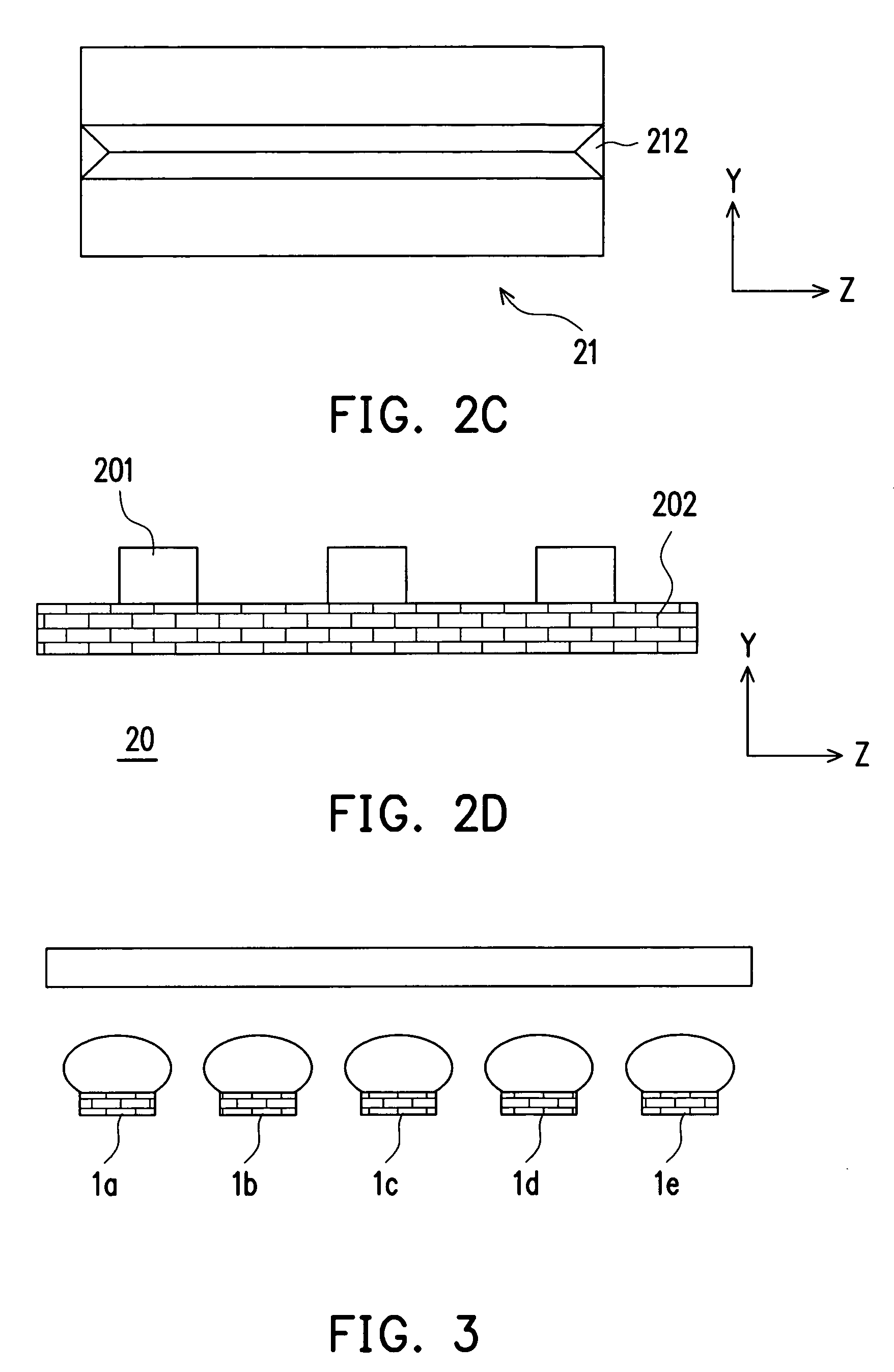
[0042]FIG. 2A is a cross-sectional view showing the tube type LED light source of the present invention along the x-axis. FIG. 2B is a cross-sectional view showing a light guide of the tube type LED light source of the present invention along the x-axis. FIG. 2C is a top view showing a light guide of the tube type LED light source of the present invention. FIG. 2D is a cross-sectional view showing a light source generator of the tube type LED light source of the present invention along the z-axis. Please refer to FIGS. 2A and 2D, the tube type LED light source 1 mainly comprises a light source generator 20, a light guide 21 and a diffuser 22. The light source generator 20 comprises a plurality of L...


PUM

PropertyMeasurementUnit
brightnessaaaaaaaaaa

Abstract

A tube type light emitting diode light source including a light source generator, a light guide and a diffuser is provided. The light source generator includes LEDs arranging in a line. The light guide has a grooved light incident surface and a grooved light-guiding surface. The grooved light incident surface encompasses the LEDs, and the grooved light-guiding surface is adapted for changing the propagating direction of an incident light. The diffuser covers the light guide.

Description

CROSS-REFERENCE TO RELATED APPLICATION [0001] This application claims the priority benefit of Taiwan application serial no. 93139034, filed on Dec. 15, 2004. All disclosure of the Taiwan application is incorporated herein by reference. BACKGROUND OF THE INVENTION [0002] 1. Technical Field [0003] The present invention generally relates to a light emitting diode (LED) light source and, in particular, to a tube type LED light source. [0004] 2. Description of the Related Art [0005] A liquid crystal display (LCD) is a non-self luminescent flat panel display which includes a flat light source device. The flat light source device is a so-called backlight module. There are two types of backlight modules: direct-light type and edge-light type backlight modules. A conventional direct-light type backlight module comprises a plurality of light tubes (such as cold cathode fluorescent lamps), a diffuser sheet, a prism sheet, and so on. Light generated from the light tubes is reflected back or par...

Claims


Application Information

Patent Timeline
Patent Type & Authority Applications(United States)
IPC IPC(8): F21V5/00F21S2/00F21V5/04F21V29/00F21Y101/02G02F1/13357H01L33/48H01L33/58H01L33/60
CPCF21K9/00F21K9/52F21Y2101/02F21K9/61F21Y2115/10G02F1/1335
Inventor HSIEH, MIN-HSUNYIN, CHOU-CHIHHSU, CHIA-LIANGWANG, JEN-SHUITSAI, CHIA-FENWANG, CHIEN-YUAN
Owner EPISTAR CORP
Learn More