Coil form

a technology of coils and coils, applied in the field of coils, can solve the problems of poor leakage inductance, heat dissipation, and suited for high-power applications, and achieve the effect of improving heat dissipation capabilities

Inactive Publication Date: 2006-06-15
DET INT HLDG LTD
View PDF8 Cites 4 Cited by
  • Summary
  • Abstract
  • Description
  • Claims
  • Application Information

AI Technical Summary

Benefits of technology

[0008] It is therefore an object of the invention to provide a coil form of the kind initially mentioned, particularly to provide a coil form for forming of a small transformer with enhanced heat dissipation capabilities.
[0009] A coil form according to an object of the invention is designed to form an inductive element with a magnetic core and at least one coil. The coil form includes a hollow coil body for insertion of the core and an outer surface for holding the coils. The coil form further includes at least one separating plate which surrounds the outer surface of the coil body and thereby divides the surface into at least one coil area. While the coil body is made of plastic, the separating plate is made of metal and has an opening for pushing the separating plate over the coil body. The separating plate further has a slit which prohibits leakage currents within the separating plate.
[0010] Fabricating the separating plate from metal results in several advantages of the invention. First of all, the metallic plate helps to dissipate the heat which is generated either within the plate or within the coils which are positioned directly adjacent to the plate. Efficient cooling of the inductive element can be achieved. Another advantage is that the separating plate serves as a side support for the coils that are provided within the coil area or coil areas. Furthermore, the metallic plates have a positive effect on the leakage inductances and the overall stability of the coil form.
[0022] Although one metal separating plate would be sufficient to provide an inductive element according to the invention, in some applications, the inductive element advantageously includes a plurality of metal separating plates. This can be done for example to increase the number of coil areas or, where the separating plates form a winding of a coil, to increase the number of windings of such a coil.
[0023] In order to increase the number of windings of a plate winding coil, two or more separating plates can be provided directly one after the other without forming any coil areas between two adjacent plates. To prevent short circuits between two adjacent separating plates, an isolation plate (electrical isolation) is provided between two adjacent separating plates. The shape of such an isolation plate corresponds to the shape of the separating plates. As an isolation plate does not conduct electrical current, there is no slit necessary in an isolation plate.

Problems solved by technology

One of the major problems when reducing the size of inductive elements is to dissipate the heat, which is generated within the magnetic circuit, efficiently.
Since this transformer does not include an efficient cooling of the circuit, it is not suited for high power applications and its leakage inductance is quite bad.
This transformer too does not provide for efficient cooling.
Furthermore, this type of transformer can not be used in applications, where at least one of the transformer windings shall be realised with isolated copper wires.
Furthermore, different cooling methods are known to enhance heat dissipation.
However, while planar transformers are suited very well in certain applications, they are not useful in other applications.

Method used


Image

  • Coil form
  • Coil form
  • Coil form

Examples


Embodiment Construction

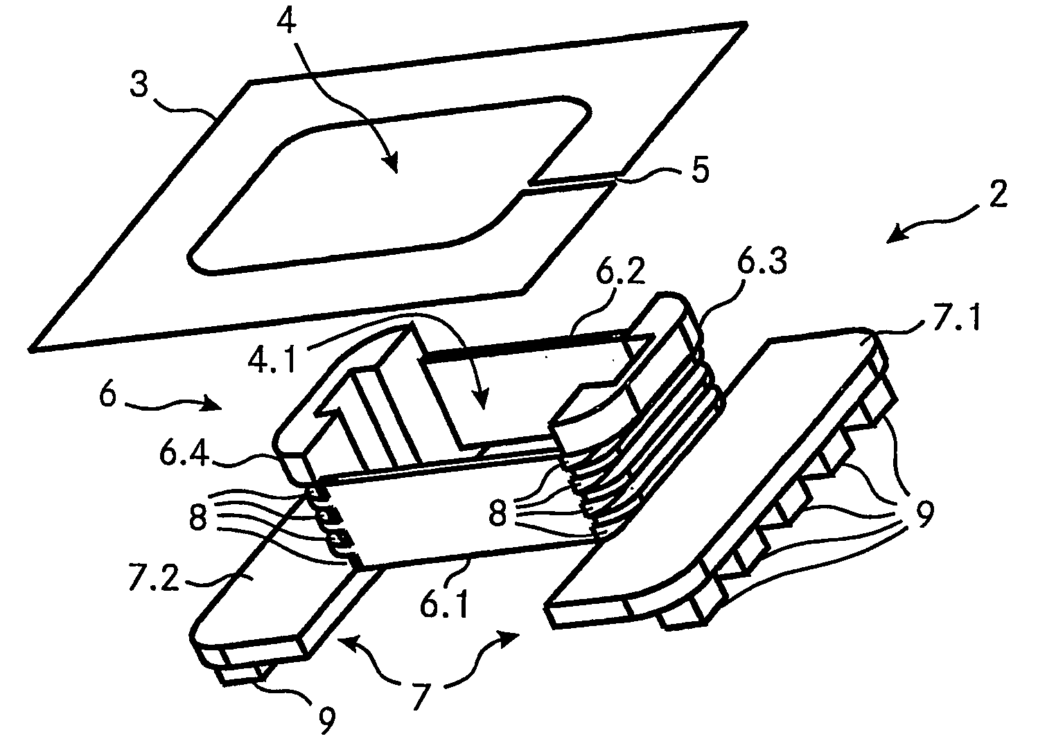
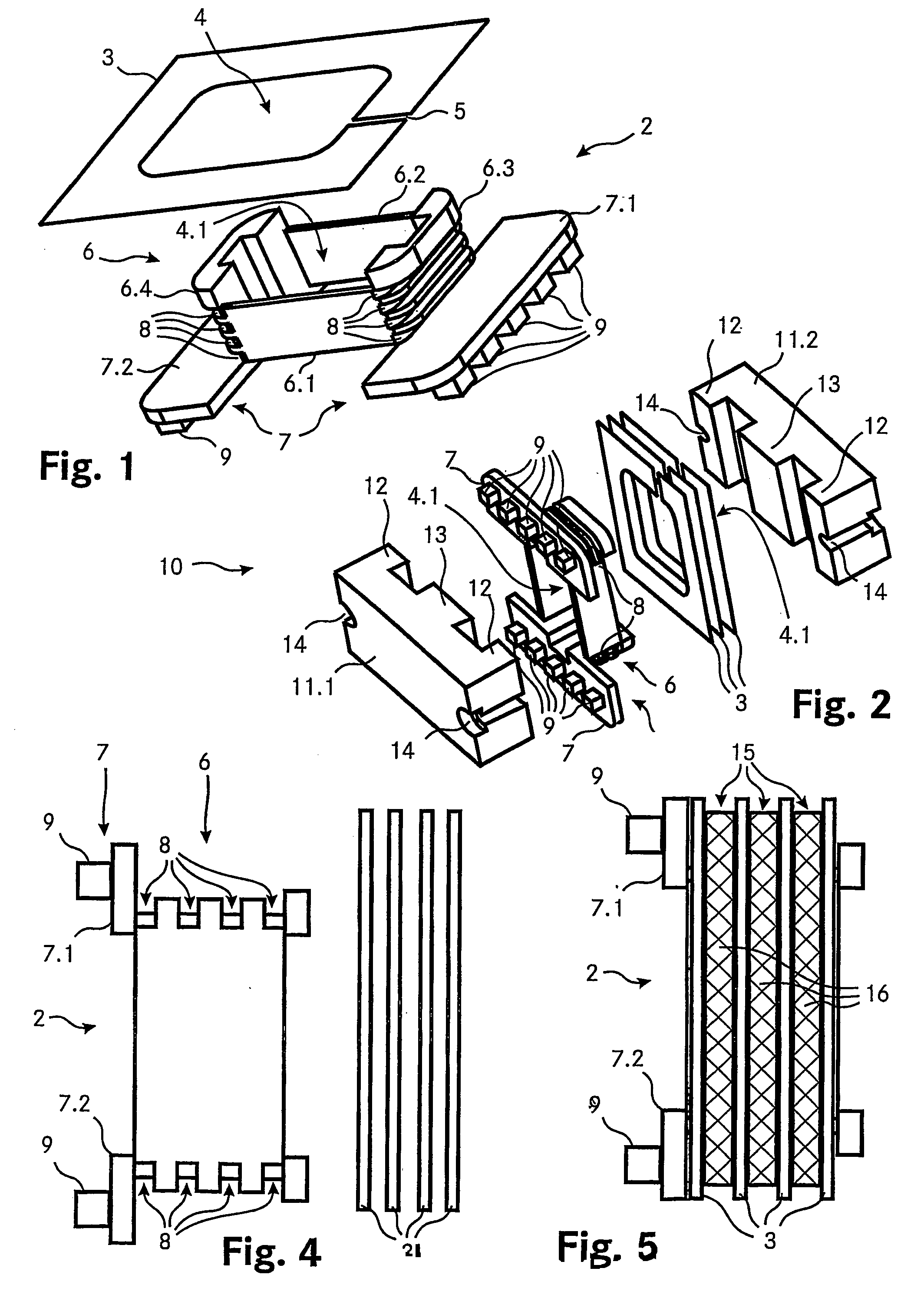
[0043]FIG. 1 shows a perspective view of the coil form 1 according to an embodiment of the invention. The coil form 1 includes a coil body 2 and a separating plate 3. The separating plate 3 is for example made of copper or aluminium or any other metal with high heat conducting capabilities and has a thickness of about 0.3 mm to 0.5 mm. The separating plate 3 has a rectangular shape, comprises an opening 4 with rectangular shape as well and includes a slit 5 which is directed from the outer boarder to the opening 4, thereby interrupting any conductive path around the opening 4 of the separating plate 3.

[0044] The coil body 2 comprises a coil portion 6 and a flange portion 7. The coil portion 6 has substantially the shape of a hollow right cylinder with four side walls 6.1, 6.2, 6.3, 6.4 around an opening 4.1 for insertion of a magnetic core (not shown) of a transformer. The flange portion 7 is divided into two flange parts 7.1, 7.2, where each flange part 7.1, 7.2 is connected to on...


PUM

PropertyMeasurementUnit
thicknessaaaaaaaaaa
areaaaaaaaaaaa
electrically conductivelyaaaaaaaaaa

Abstract

A coil form for forming an inductive element (10) includes a coil body (2) and at least one, for example three separating plates (3). The coil body (2) has an opening (4.1) and includes two portions, a coil portion (6) and a flange portion (7). To put the inductive element (10) together, the separating plates (3) are pushed over the coil portion (6) of the coil body (2). For positioning of the separating plates (3), recesses (8) are provided on the surface of the coil portion (6). The separating plates (3) divide the surface of the coil portion (2) into a plurality of coil areas where the coil or the coils of the inductive component (10) can be provided, for example by winding an isolated wire around the coil portion (6) in a coil area. Afterwards, the core of the inductive component is installed by fitting the two E-shaped core parts (11.1, 11.2) together such that the middle leg (13) of each core part (11.1, 11.2) is inserted into the opening (4.1) of the core body (2).

Description

TECHNICAL FIELD [0001] The invention relates to a coil form for forming an inductive element with a core and at least one coil, the coil form including a hollow coil body for insertion of the core, the coil body having an outer surface for holding the at least one coil and the coil form further including at least one separating plate which surrounds the outer surface of the coil body thereby dividing the surface into a least one coil area. The invention further relates to an inductive element with such a coil form and a coil form having a hollow coil body for insertion of a core of an inductive element and having an outer surface for holding a coil of the inductive element. BACKGROUND [0002] In the manufacturing of electric and / or electronic components exists an ongoing demand for smaller components while their power density should be increased at the same time. This is particularly true in the manufacturing of inductive elements such as transformers, inductors or chokes. One of the...

Claims


Application Information

Patent Timeline
Patent Type & Authority Applications(United States)
IPC IPC(8): H01F27/30H01F5/02H01F27/22H01F27/28H01F27/32
CPCH01F5/02H01F27/22H01F27/2823H01F27/2847H01F27/2866H01F27/306H01F27/325H01F2005/043
Inventor PILNIAK, JURGEN
Owner DET INT HLDG LTD
Why Eureka
Try Eureka