
Method and apparatus for the analysis of complex systems

a technology for complex systems and methods, applied in the field of methods and apparatus for the analysis of complex systems, can solve the problems of complex behaviour, difficult to understand, predict and manage, and achieve the effects of facilitating the loading of architecture storing means, facilitating the entry of architecture data, and facilitating analysis of the architectur

Inactive Publication Date: 2006-06-08
AVOLUTION
View PDF8 Cites 19 Cited by
  • Summary
  • Abstract
  • Description
  • Claims
  • Application Information

AI Technical Summary

Benefits of technology

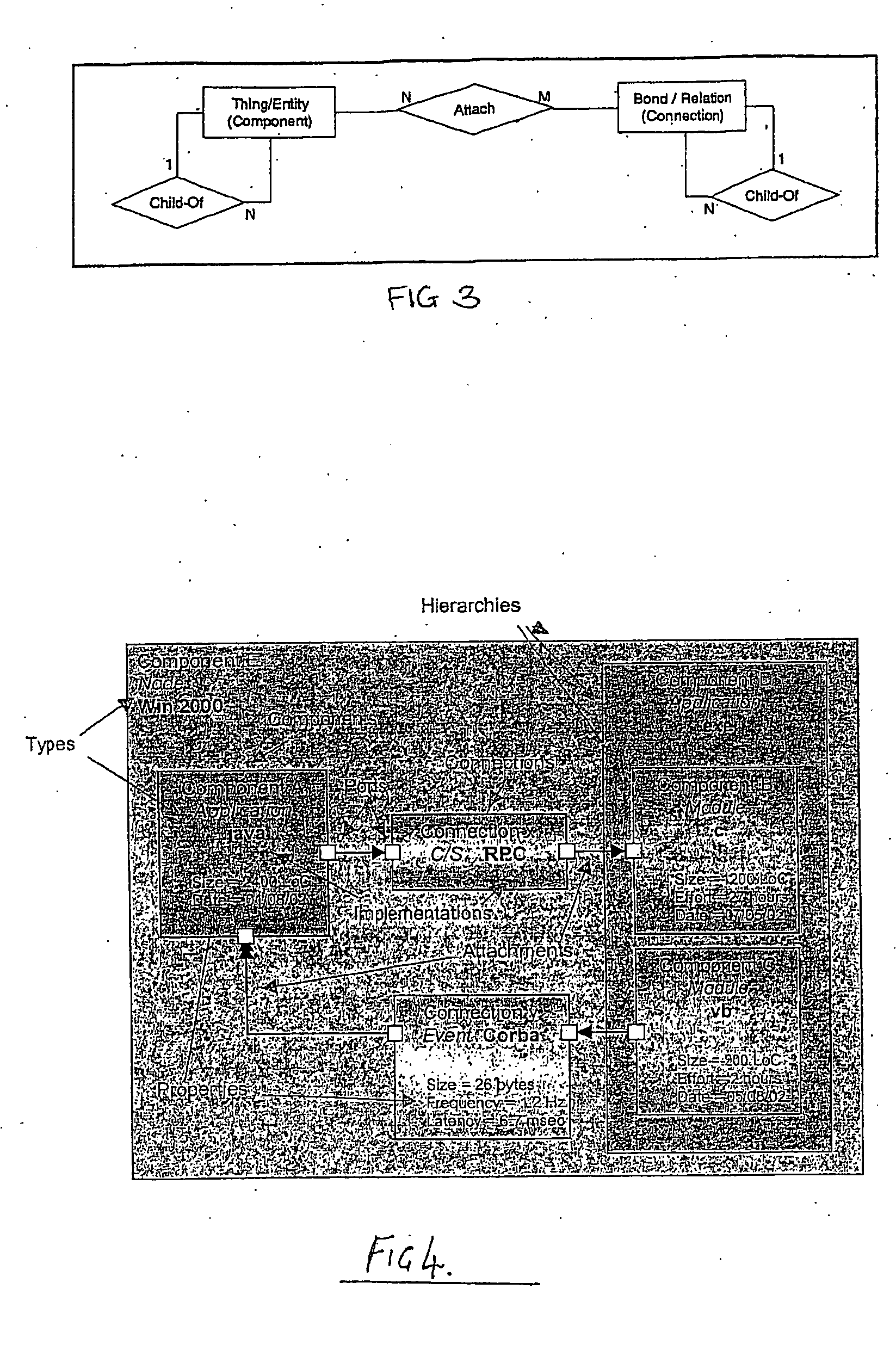
[0016] Advantageously, utilising the simple component / connection model, complex architectures can conveniently be represented and evaluated.
[0022] The visualisation means providing a plurality of different types of visualisation of the architecture advantageously enables a user to represent and evaluate different aspects of the complex system, much in the same way as in the built environment (eg. architectural approach to buildings), the scale model, mechanical drawings and electrical schematics allow architects and builders the ability to visualise different aspects of a building.
[0024] Preferably, the visualisation means may also be used to facilitate loading of the architecture storing means with the architecture information. For example, in one further embodiment an interface is provided which enables a user to build a tree view of the architecture. The interface facilitates entry of architecture data in a tree view form.
[0026] Preferably, the apparatus of the present invention enables the architecture to be modelled at different levels of detail. This can facilitate analysis of the architecture at different levels, for example at different levels within an organisation. This can be extremely useful. For example, at a very high level, a board of directors may only wish to view a high level of architecture to confirm that the system has the functionality they require for their organisation. They may wish to utilise the apparatus of the present invention to re-model the system at that very high level. At the other end of the scale, an implementation architecture may be required to be modelled by a software engineer who is implementing the software at the most detailed level. The apparatus of the present invention preferably enables the architecture to be modelled at any level.

Problems solved by technology

This leads to complex behaviour which is difficult to understand, predict and to manage.

Method used


Image

  • Method and apparatus for the analysis of complex systems
  • Method and apparatus for the analysis of complex systems
  • Method and apparatus for the analysis of complex systems

Examples


Embodiment Construction

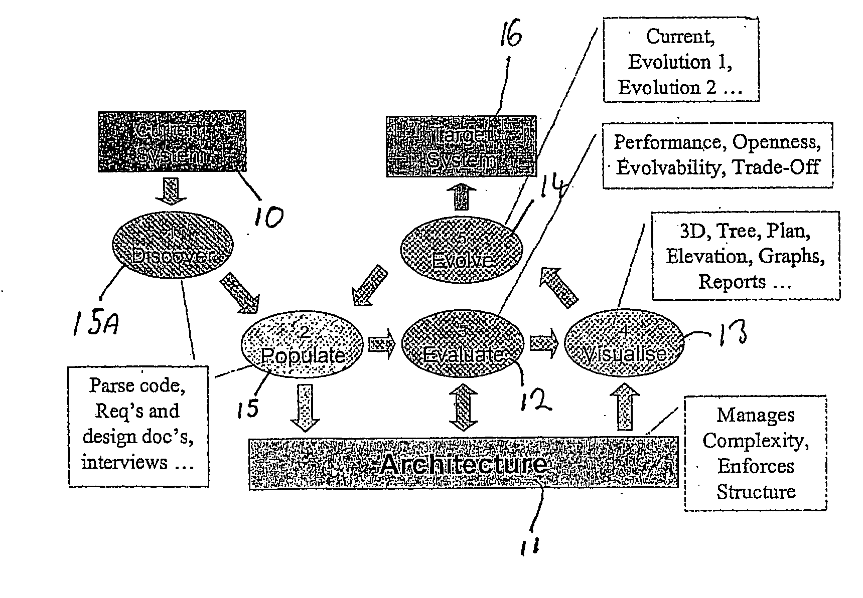
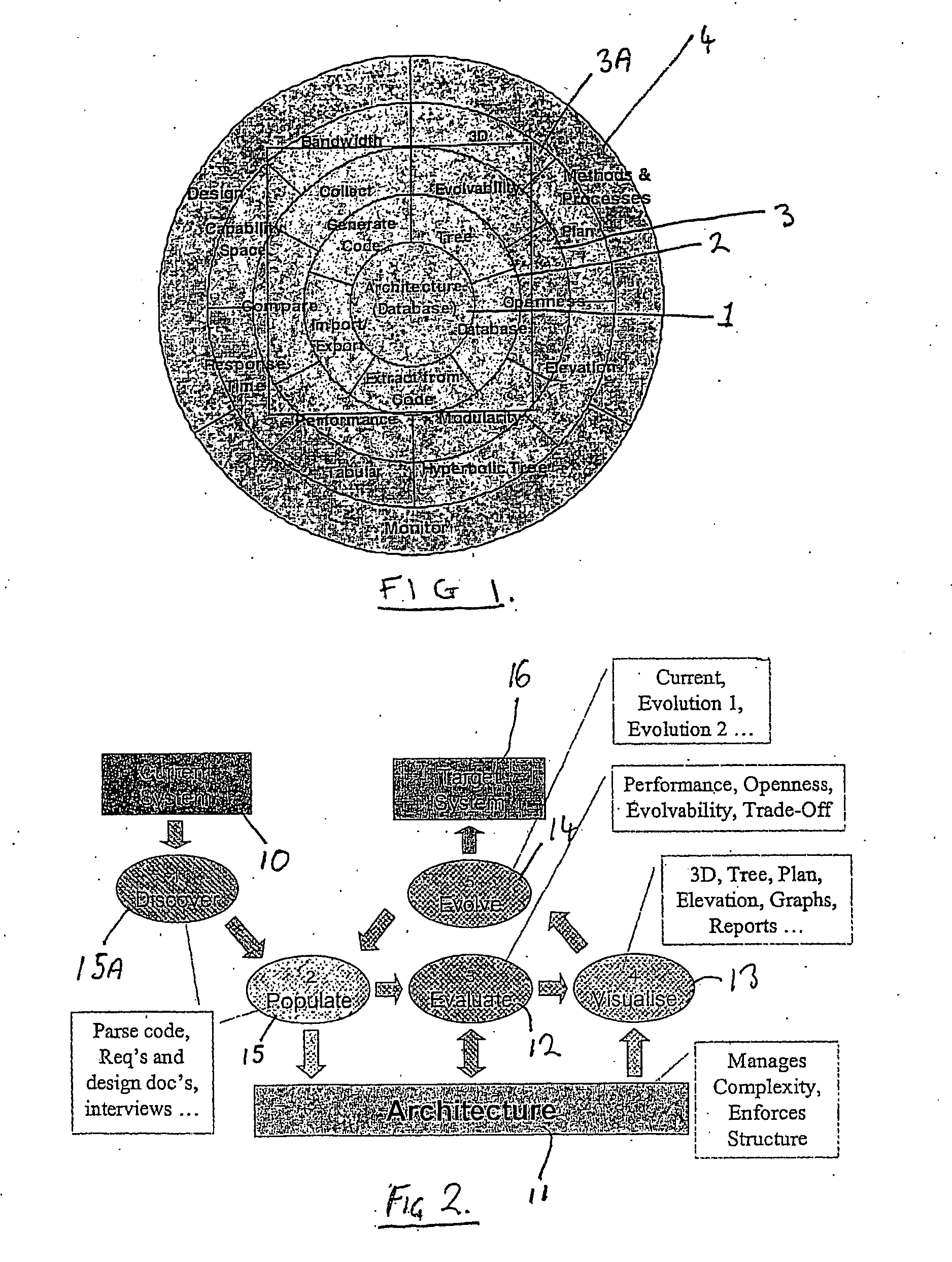
[0055]FIG. 1 is a schematic diagram representing a high level view of an apparatus in accordance with an embodiment of the present invention, this embodiment being a tool for analysis of a complex system, which can be utilised for the purposes of engineering (developing and amending) the complex system and / or evaluating the complex system. The tool may utilise any appropriate software / hardware platform to implement the tool providing the functionality as described in the following. In this embodiment, a computing system such as schematically illustrated in FIG. 22 is utilised to implement the apparatus. The computing system includes a computer 100 which incorporates conventional computing hardware, such as a processor(s) ROM, RAM, disc memory means. The system also includes a user interface comprising a keyboard 101 and mouse 102 for input, and a monitor 103 for display of information. It will be appreciated that the elements illustrated in the high level diagram of FIG. 1 to be des...


PUM


Abstract

The present invention relates to a method and apparatus for the analysis, particularly, of computing systems. The invention implements an architecture based analysis. The architecture of the system to be analysed is first of all modelled, using a hierarchical model comprising Connections, Components, and other entities. The modelling requires the steps of obtaining the architecture of the system and populating a database or file with the architecture model. The modelled architecture is then evaluated, probably by running simulations of operation of the architecture and also by visualising the architecture using a number of different visualisations. Following the evaluation, changes may be imposed to the architectural model and to the system in order to meet non-functional requirements.

Description

FIELD OF THE INVENTION [0001] The present invention relates to a method and apparatus for the analysis of systems, particularly, but not exclusively, complex systems, and particularly, but not exclusively, to a method and apparatus for analysis of computing systems. BACKGROUND OF THE INVENTION [0002] There are many known types of computing systems, of varying levels of complexity and utilising various types of software and hardware platforms. Such systems play critical roles in organisations and indeed in society. We are now becoming increasingly reliant on them. [0003] Any computing system can be considered in terms of functional requirements and non-functional requirements. The functional requirements are those which it is stated that the system can achieve in day to day operation. For example, a billing system must have the requisite algorithms and business processes to achieve the billing requirements of an organisation (which might be quite complex, for example in the case of a...

Claims


Application Information

Patent Timeline
IPC IPC(8): G06Q99/00G06F17/50
CPCG06F17/5009G06F2217/06G06F30/20G06F2111/04
Inventor DENFORD, MARKLEANEY, JOHNO'NEILL, TIMROWE, DAVID
Owner AVOLUTION
Learn More