
Power control apparatus and method for electrical system of vehicle

a technology of power control apparatus and electrical system, which is applied in non-electric variable control, process and machine control, instruments, etc., can solve the problems of inability to achieve effective fuel consumption improvement, varies in power cost, and may not always be minimized the average power cost of the entire electrical system, so as to achieve the effect of improving fuel consumption

Active Publication Date: 2006-06-08
DENSO CORP
View PDF5 Cites 62 Cited by
  • Summary
  • Abstract
  • Description
  • Claims
  • Application Information

AI Technical Summary

Benefits of technology

[0006] It is an object to provide a power control apparatus for an electrical system of a vehicle that stabilizes a bus voltage of an electrical system and improves fuel consumption.
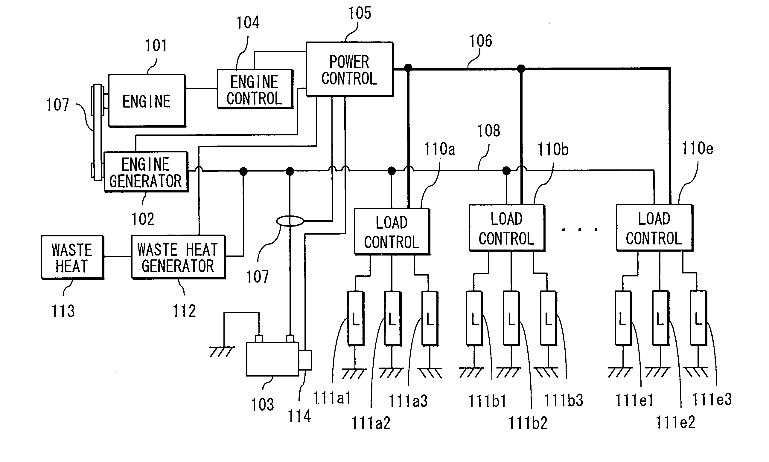
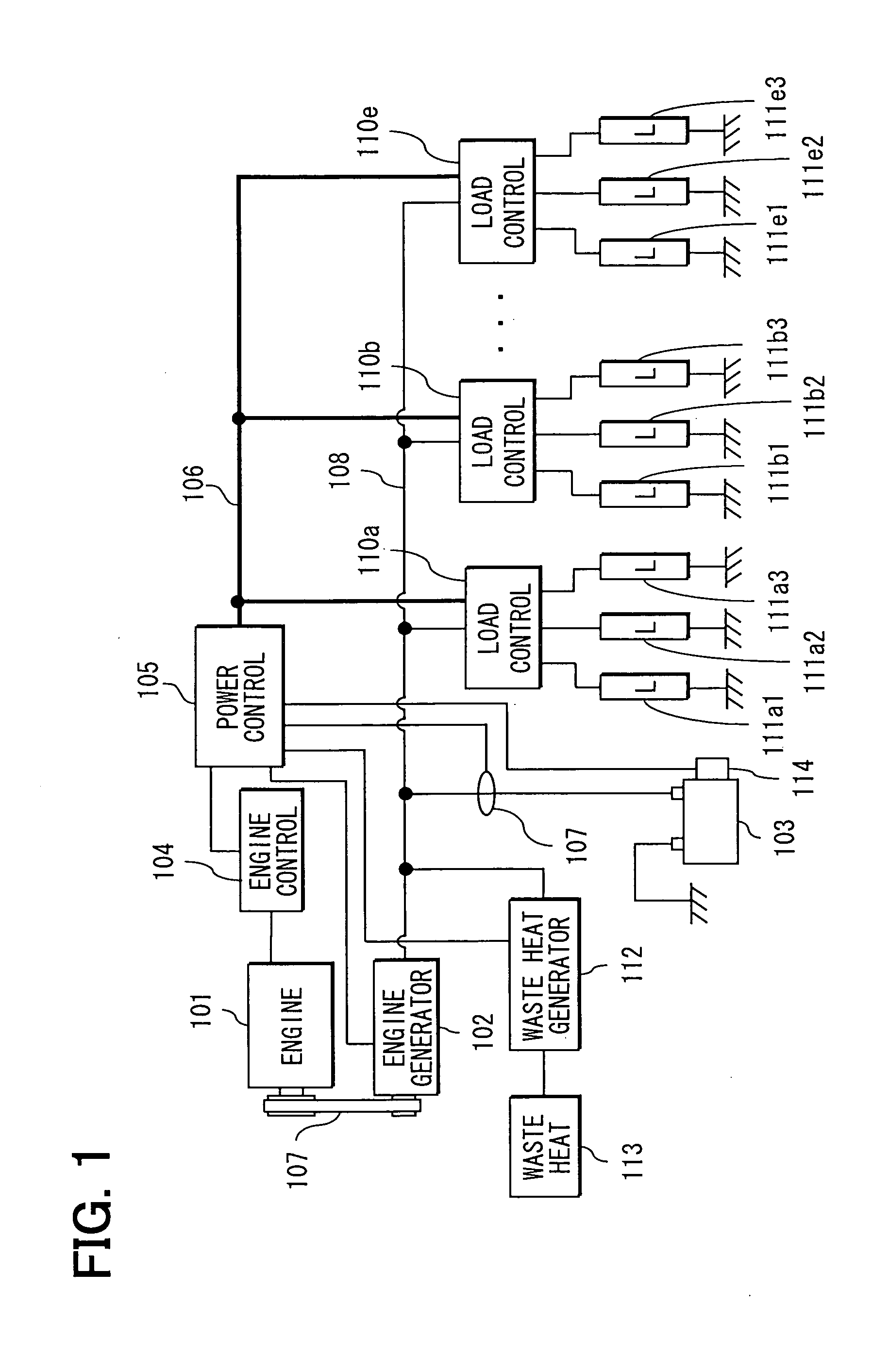
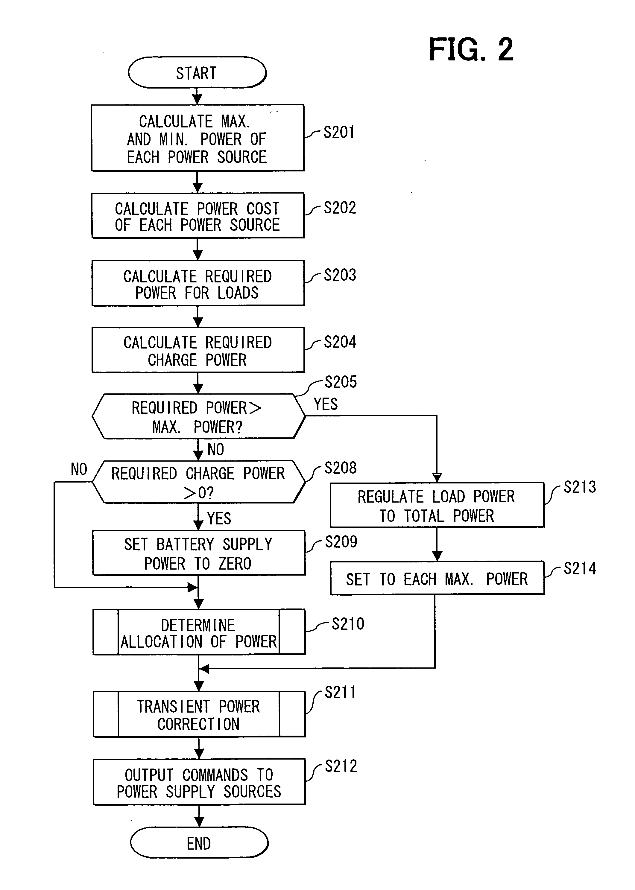
[0007] According to one aspect, a power control apparatus for an electrical system supplies power from a plurality of power supply sources to an electrical load. The apparatus determines an allocation amount of power for each of the power supply sources so that a power cost of an entirety of the electrical system is minimized, by taking into account a variation in a power cost, which is indicative of a cost per unit amount of power, with respect to a supply amount of each of the power of respective power supply sources. The apparatus controls power generation of each of the power supply sources in accordance with a determined allocation amount of power.

Problems solved by technology

In many cases, the power cost varies with variations in a supply amount of power.
Thus, the average power cost of the entire electrical system may not always be minimized, so that effective fuel consumption improvement cannot be achieved.
Further, according to the above control method, characteristics such as response characteristics of the respective power energy supply sources are not taken into account.
For example, a necessary consumption amount of power sharply varies.
When the response of a power energy supply source with respect to a power generation command is slow, there will occur excessive power generation or deficient power generation.
Consequently, the supply voltage from a power bus to electric loads becomes unstable.

Method used


Image

  • Power control apparatus and method for electrical system of vehicle
  • Power control apparatus and method for electrical system of vehicle
  • Power control apparatus and method for electrical system of vehicle

Examples


first modification

[0083] (First Modification)

[0084] According to the present embodiment, as shown in FIG. 4, the target cost is set in accordance with the battery residual capacity. However, as shown in FIG. 7, the target cost may be set higher as the load-required amount of power increases. Accordingly, the target cost can be set high when the load-required amount of power is large, whereby the reduction in the battery power can be minimized, and hence battery shutdown can be prevented.

second modification

[0085] (Second Modification)

[0086] As shown in FIG. 12A, a response delay element PE(s) of the engine output torque can be incorporated in the control system shown in FIG. 9. In this case, torque information of torque actually outputtable with the delay can be used, thereby enabling control to be performed in accordance with a value of the information. Consequently, engine torque insufficiency can be prevented from occurring in the event of power generation (supply), and hence desired drivability of the vehicle can be secured.

[0087] In addition, as shown in FIG. 12B, with the response delay element PE(s)′ provided subsequent to the plant P(s), the configuration can be simplified. In this case, in the discretization model G(z) shown in FIG. 9, P(s) and PE(s)′ can be handled as a single element.


PUM


Abstract

A power control apparatus acquires a maximum supply amount of power, transient maximum supply amount of power, and transient minimum supply amount of power of each power supply source. The apparatus further acquires a power cost of respective power supply sources, a load-required power and a charge request power. The apparatus acquires a combination of power supply sources that minimizes specific fuel consumption and determines an allocation amount of power. Taking transient response of respective power supply sources into account, the allocation amount of power of each power supply sources is corrected to be greater than a transient minimum supply power and smaller than a transient maximum supply power.

Description

CROSS REFERENCE TO RELATED APPLICATION [0001] This application relates to and incorporates herein by reference Japanese Patent Application No. 2004-356030 filed on Dec. 8, 2004. FIELD OF THE INVENTION [0002] The present invention relates to a power control apparatus and method for an electrical system of a vehicle. BACKGROUND OF THE INVENTION [0003] US 2004 / 0164616-A1 (JP 2004-260908A) proposes methods for controlling a vehicle electrical system that controls a power cost of a vehicle electrical system, thereby to enhance fuel cost improvement. This control method of an electrical system of a vehicle (vehicle electrical system) is carried out in two steps. In one step, the method obtains or calculates information of power costs each coinciding with a cost per unit amount of electric power of respective one of power energy supply sources, such as the source of engine power generation and regenerative power generation. In accordance with the information thus acquired, in the other ste...

Claims


Application Information

Patent Timeline
IPC IPC(8): H02J4/00H02J7/34
CPCB60R16/03H02J1/00H02J4/00H02J2310/46
Inventor TANI, KEISUKEOBAYASHI, KAZUYOSHISENDA, TAKASHITAMURA, HIROSHI
Owner DENSO CORP
Learn More