
Grinding method of crank pin and grinding machine

Inactive Publication Date: 2006-06-08
TOYODA MASCH WORKS LTD
View PDF14 Cites 7 Cited by
  • Summary
  • Abstract
  • Description
  • Claims
  • Application Information

AI Technical Summary

Benefits of technology

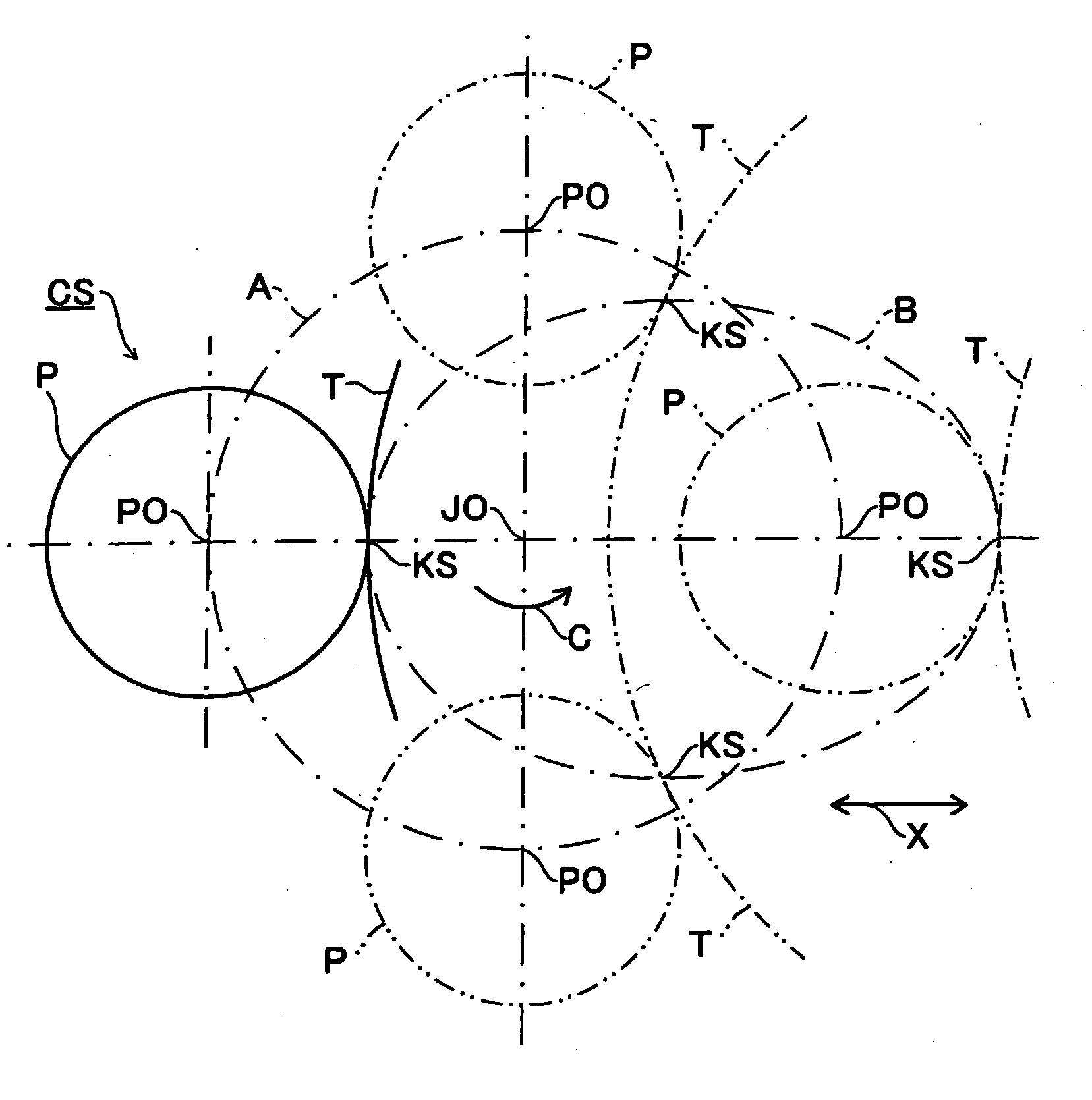
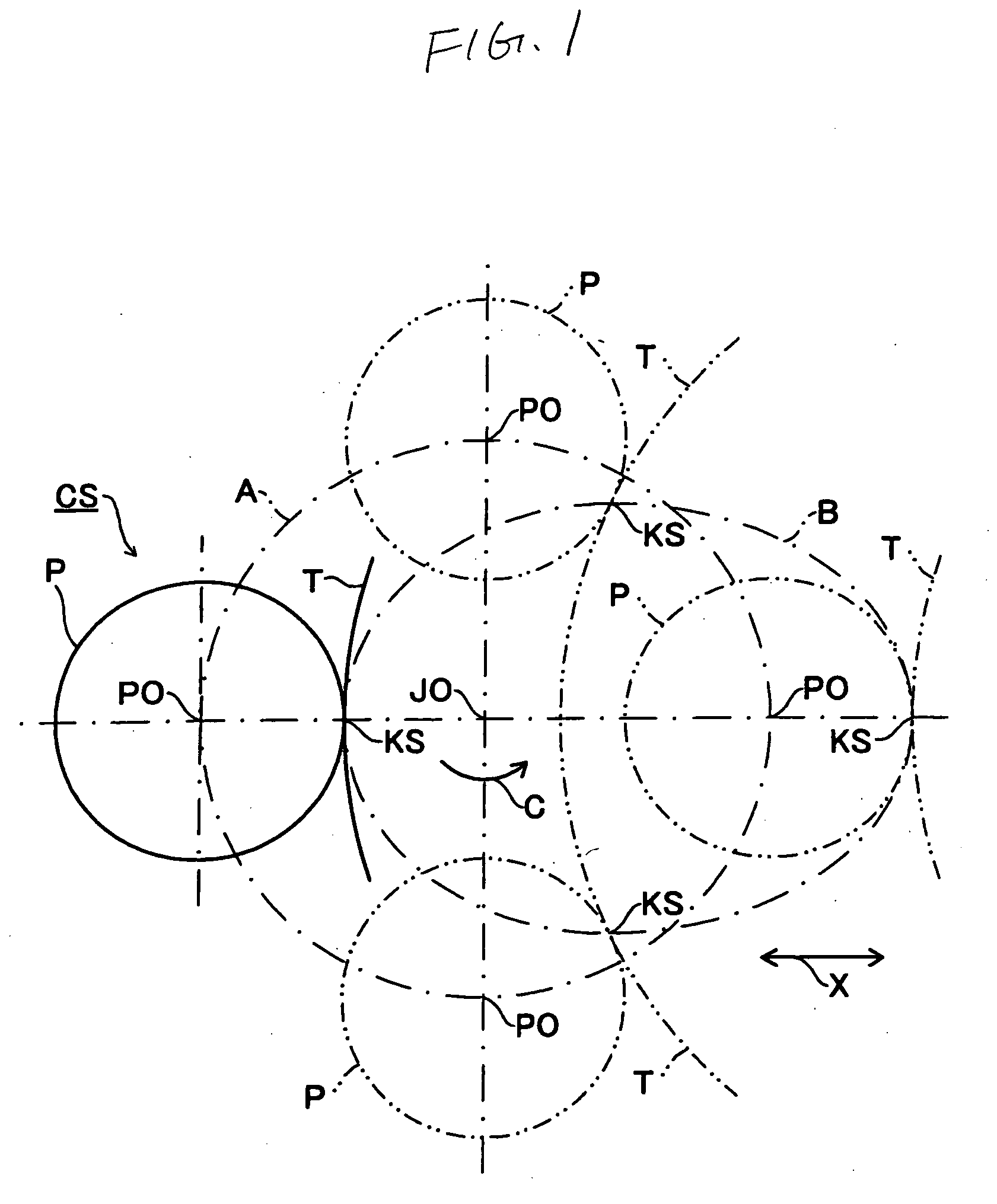
[0008] Still furthermore, the grinding portion KS is changed to be revolved around the journal center JO, the rotation center of the crankshaft CS. More specifically, the grinding portion KS moves in an elliptical orbit in one revolution of the crankshaft CS (one-dotted line B). Therefore, the grinding speed, the grinding ef

Problems solved by technology

Furthermore, the changed grinding speed affects the grinding efficiency or abrasive grain load essentially.
Furthermore, if the grinding conditions are changed variously in one revolution of the crankshaft CS, it is impossible to obtain grinded surfaces having uniform surface roughness throughout the outer circumferential surface of the crank pin P. Therefore, the grinding method in the related art cannot meet the requirement of making the surface roughness uniform throughout the outer circumferential surface of the crank pin P.

Method used


Image

  • Grinding method of crank pin and grinding machine
  • Grinding method of crank pin and grinding machine
  • Grinding method of crank pin and grinding machine

Examples


embodiment 1

[0022] At grinding portions KS, at which the grinding wheel T comes into contact with the crank pin P, the rotation number of the crankshaft CS is changed according to a rotation phase angle of the crankshaft CS in order to make constant the relative speed between an outer circumferential surface of the grinding wheel T and an outer circumferential surface of the crank pin P or to make the change in the relative speed between the outer circumferential surface of the grinding wheel T and the outer circumferential surface of the crank pin P small comparing with the constant rotation number of the crankshaft CS, that is, to make the relative speed almost constant.

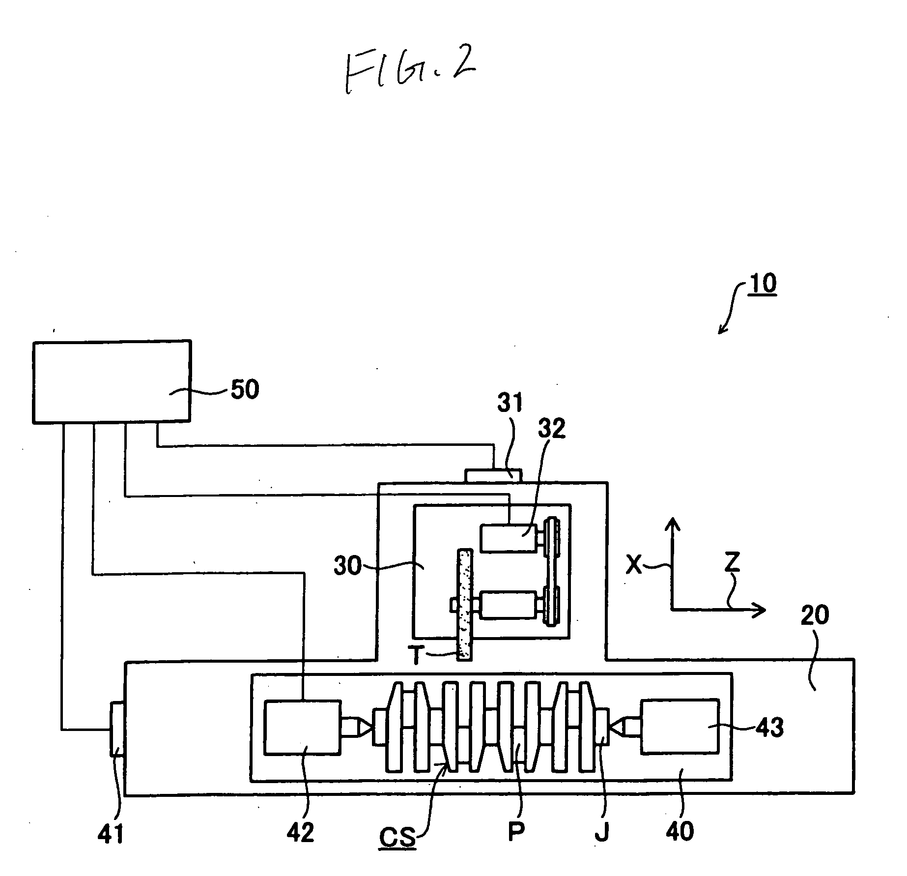
[0023] For example, the rotation number of the crankshaft CS by the rotation phase angle of the crankshaft CS is extracted from fixed values defined by the shapes of the crankshaft CS or the grinding wheel T such as “the diameter of the crank pin P”, “the distance between a journal center JO and a center axis of the crank pin...

embodiment 2

[0027] In one revolution of the crankshaft CS, since the grinding portions KS deviate vertically from the surface connecting the journal center JO and the rotation center of the grinding wheel T, the position of the crank pin P with respect to the grinding wheel T is changed. Therefore, the grinding efficiency and abrasive grain load are affected by the change in the position of the crank pin P as well as the change in the grinding speed. Therefore, the rotation number of the crankshaft CS is changed according to the rotation phase angle of the crankshaft CS in order to make constant the relevant indices such as grinding efficiency, abrasive grain load or the like on the basis of fixed values such as “the diameter of the crank pin P”, “the eccentric amount of the crank pin P”, “the diameter of the grinding wheel T” or the like; theoretical values extracted from fixed values or the like such as “grinding-removal allowance”; or estimated values extracted while some fixed values are om...

embodiment 3

[0029] When the crankshaft CS is revolved at a constant rotation number, there can be portions having superior surface roughness than required value and portions capable of enduring severer grinding conditions, for example, portions without grinding burn even at a higher grinding speed, throughout the outer circumferential surface of the crank pin P. Therefore, the rotation phase angles at the above portions are extracted as the theoretical values extracted from the various fixed values described above or values measured after an actual process, and then the rotation number of the crankshaft CS is changed to make the rotation number fast at the rotation phase angles.

[0030] Then, the process time can be shortened.


PUM

PropertyMeasurementUnit
Angleaaaaaaaaaa
Speedaaaaaaaaaa

Abstract

A grinding method of a crank pin that grinds an outer circumferential surface of the crank pin of a crankshaft having a crank journal and the crank pin eccentric to the crank journal by rotating a crankshaft around a central axis (a center of the journal) of the crank journal and moving a rotating grinding wheel in a diametric direction of the crankshaft according to rotation phase angle of the crankshaft, in which a rotation number of the crankshaft is changed in one revolution of the crankshaft to perform a grinding process.

Description

CROSS-REFERENCE TO RELATED APPLICATIONS [0001] This application is based on and claims the benefit of priority from the prior Japanese Patent Application No. 2004-350997, filed on Dec. 3, 2004; the entire contents of which are incorporated herein by reference. BACKGROUND OF THE INVENTION [0002] 1. Field of the Invention [0003] The present invention relates to a grinding method of a crank pin, and particularly to the grinding method of the crank pin that grinds an outer circumferential surface of a crank pin by rotating a crankshaft having the crank journal and the crank pin eccentric to a crank journal around a central axis of the crank journal and moving a rotating grinding wheel T in a diametric direction of the crankshaft CS according to a rotation phase angle of the crankshaft. The present invention also relates to a grinding machine performing such method. [0004] 2. Description of the Related Art [0005] A crankshaft includes a crank journal and a crank pin eccentric to the cran...

Claims


Application Information

Patent Timeline
IPC IPC(8): B24B51/00B24B1/00
CPCB24B5/42B24B47/22
Inventor HORI, NOBUMITSUNONOYAMA, MAKOTOOKADA, KIKUTOSHI
Owner TOYODA MASCH WORKS LTD
Learn More