
A circuit for generating a voltage waveform at an output node

Active Publication Date: 2018-10-18
SHIMADZU CORP
View PDF2 Cites 0 Cited by
  • Summary
  • Abstract
  • Description
  • Claims
  • Application Information

AI Technical Summary

Benefits of technology

The patent discusses a method of controlling the voltage at the output of a circuit using two anchor voltages. These anchor voltages are placed between the first and second voltages and are used to help the output voltage swing closer to the anchor voltages, reducing the amount of current drawn from the first and second voltage rails. This helps to stabilize the first and second voltages and is useful in applications where stable voltages are needed, such as mass spectrometry. By using this method, the patent proposes that the output voltage can be controlled more efficiently, leading to improved performance and reliability of the circuit.

Problems solved by technology

However, “hard switching” techniques (described in more detail below), tend to be inefficient and power consumption is relatively large.
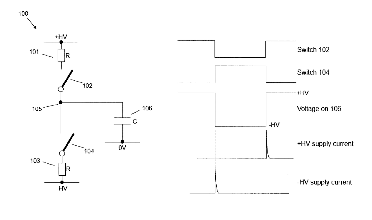
However, whilst the circuits proposed by EP2806553 provide a significant improvement in energy efficiency compared with “hard switching” techniques in which resonant circuits are not used (e.g. as disclosed in WO01 / 29875), the present inventors have found that the “energy recovery” circuits proposed in EP2806553 still result in a significant amount of current to be drawn from high voltage power supplies typically used in generating the voltage waveform, which can cause a lack of stability in the voltages provided by the high voltage power supplies (which may be highly problematic in certain applications, such as mass spectrometry).

Method used


Image

  • A circuit for generating a voltage waveform at an output node
  • A circuit for generating a voltage waveform at an output node
  • A circuit for generating a voltage waveform at an output node

Examples


Embodiment Construction

[0090]Polarity switching is an important feature of all types of ToF mass spectrometers and is particularly suited to Ion Trap ToF mass spectrometers. Faster switching improves throughput, duty cycle and sensitivity. In simple terms the higher the rate of switching, the better the overall performance. A problem throughout the industry is that conventionally a high rate of switching is a very difficult objective to meet for reasons outlined below.

[0091]Herein, the term “high voltage” (or simply “HV”) may be used to refer to a voltage that has a magnitude that is at least 100V, more preferably at least 1000V, with respect to a ground that may be between the first anchor voltage and the second anchor voltage. Similarly, a “high voltage” power supply may be used to refer to a voltage source that is capable of generating a voltage that has a magnitude that is at least 100V, more preferably at least 1000V, with respect to a ground that may be between the first anchor voltage and the secon...


PUM


Abstract

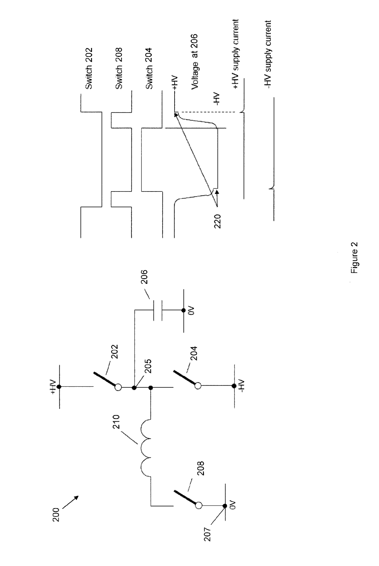
A circuit for generating a voltage waveform at an output node. The circuit includes a first voltage rail configured to be held at a first voltage, wherein the first voltage rail is connected to the output node via a first voltage rail switch; a second voltage rail configured to be held at a second voltage that is different from the first voltage, wherein the second voltage rail is connected to the output node via a second voltage rail switch; at least one anchor node connected to the output node via an inductor and an anchor node switch; and a control unit configured to switch the circuit between: a first voltage outputting state in which the first voltage rail switch is closed and the second voltage rail switch is open such that the output node is clamped to the first voltage; and a second voltage outputting producing state in which the second voltage rail switch is closed and the first voltage rail switch is open such that the output node is clamped to the second voltage. The control unit is configured to switch the circuit from the first voltage outputting state to the second voltage outputting state by: opening the first voltage rail switch and closing an anchor node switch that connects the output node via an inductor to an anchor node held at a first anchor voltage so that, if a load capacitance is connected to the output node, a resonant circuit is established between the inductor and the load capacitance causing the voltage at the output node to swing towards the second voltage, wherein the first anchor voltage is configured to provide energy that assists the voltage at the output node in swinging towards the second voltage; and then opening the anchor node switch and closing the second voltage rail switch. The control unit is further configured to switch the circuit from the second voltage outputting state to the first voltage outputting state by: opening the second voltage rail switch and closing an anchor node switch that connects the output node via an inductor to an anchor node held at a second anchor voltage so that, if a load capacitance is connected to the output node, a resonant circuit is established between the inductor and the load capacitance causing the voltage at the output node to swing towards the first voltage, wherein the second anchor voltage is configured to provide energy that assists the voltage at the output node in swinging towards the first voltage; and then opening the anchor node switch and closing the first voltage rail switch.

Description

FIELD OF THE INVENTION[0001]This invention relates to a circuit for generating a voltage waveform at an output node, e.g. for use in a mass spectrometer.BACKGROUND[0002]As described in a previous patent application by this applicant, EP2806553 (whose disclosure corresponds to that of related applications US2014 / 0347104 and CN104184309), numerous methods of performing mass spectrometry rely on the application of high frequency voltage waveforms to components of a mass spectrometer. For example, ion optical devices such as ion guides, ion traps, mass filters and other devices may all require such voltage waveforms, as is well described in the literature.[0003]The previous patent application by this applicant, EP2806553, further described that direct switching methods provide a significant advantage over resonant circuits in that the frequency of the voltage waveform can be easily changed during operation. However, “hard switching” techniques (described in more detail below), tend to b...

Claims


Application Information

Patent Timeline
IPC IPC(8): H01J49/02H03K3/012H03K17/687H02M1/00
CPCH01J49/022H03K3/012H03K17/6874H02M7/537H02M1/0058H02M7/4815Y02B70/10
Inventor TAYLOR, STEVEN DOUGLASHARLEY, STUART JOHN LAWRENCEHANDFORD, JOHN
Owner SHIMADZU CORP
Learn More