
Method of manufacturing barrier ribs for pdp by capillary molding of paste and paste compositions therefor

Inactive Publication Date: 2006-06-08
LG ELECTRONICS INC
View PDF4 Cites 17 Cited by
  • Summary
  • Abstract
  • Description
  • Claims
  • Application Information

AI Technical Summary

Benefits of technology

[0014] Second, the present invention provides a technique which is may minimize the loss of barrier rib materials so as to prevent environmental pollution due to the industrial waste created during the barrier rib forming process.
[0015] Third, the present invention provides a technique which is capable of lowering manufacture costs by simplifying the barrier rib manufacturing process for four steps such as the paste coating, the capillary tube molding, the mold removal and the sintering.
[0016] Fourth, the present invention provides a technique which is capable of manufacturing barrier ribs having excellent quality by increasing the mold release property and thus improving yield of the process and stability of the barrier rib shape.

Problems solved by technology

However, the sand blasting has drawbacks in the facts that many and complicated processes are required to manufacture the barrier ribs, the side shapes of the manufactured barrier ribs are not uniform, and the drying and coating process is executed very slowly.
However, the sand blasting is substantially impossible to obtain such thickness.
Since ceramic powder and high-pressure gas are used for etching to form the barrier ribs, it is hardly possible to make a thin barrier rib since the barrier rib is broken due to the mechanical energy of the ceramic powder and the high-pressure gas.
Thus, the sand blasting generates a large amount of wastes.
Furthermore, since the thick film has glass frit containing a large amount of lead monoxide, the wastes may cause environmental pollution.
Such etching method has some problems as follows.
First, since the barrier rib material layer formed by sintering is etched by an etching solution such as acid, environmental pollution may be caused by wasted water.
Since the layer to be etched is thick as much as 120 μm˜150 μm, an amount of the wasted water is very significant, thereby requiring much costs for treating the wasted water.
Thus, there are many limitations in selecting the material, and thus the selection of the barrier rib material is very limited.
Third, when applied to a large area, this etching method may hardly obtain a uniform etching speed.
However, to maintain the conditions throughout the large area is very hard, thereby resulting in very low process yield.

Method used

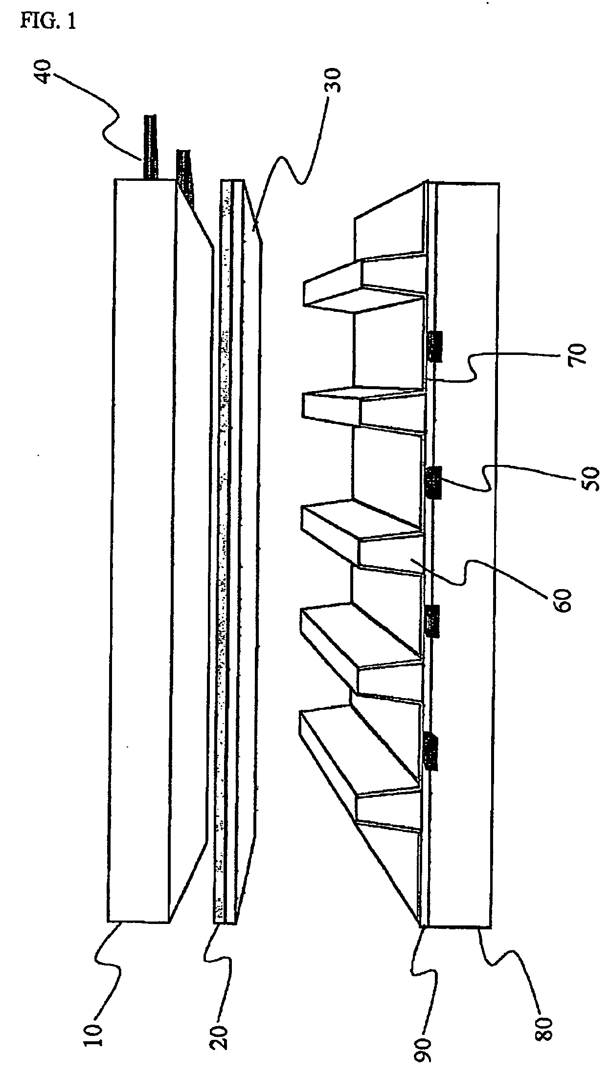
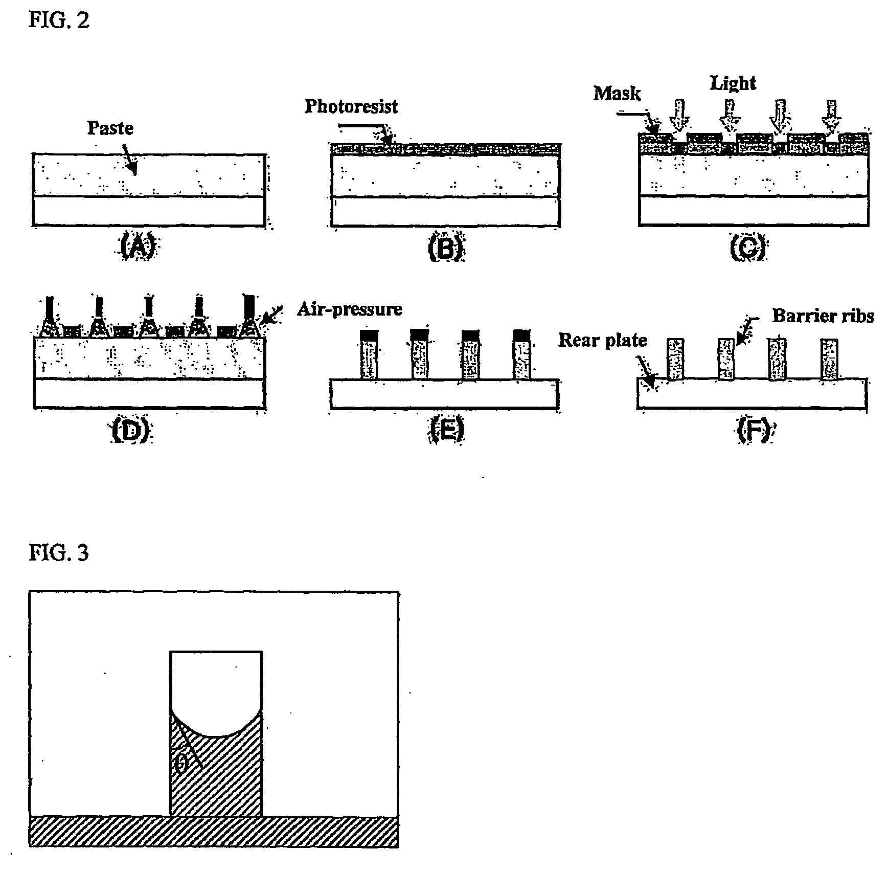

Image

  • Method of manufacturing barrier ribs for pdp by capillary molding of paste and paste compositions therefor
  • Method of manufacturing barrier ribs for pdp by capillary molding of paste and paste compositions therefor
  • Method of manufacturing barrier ribs for pdp by capillary molding of paste and paste compositions therefor

Examples


embodiment 1

[0085] 100 g of powder including glass powder and alumina powder in the ratio of 8:2 is well mixed and then ball-milled for 8 hours. To this powder mixture, 17 wt % of thermosetting resin (e.g., bisphenol A epoxy resin or cycloalkyl epoxy resin) is added on the basis of the overall powder. And then, 13 wt % of LGE (manufactured by Kookdo Chemical Co. Ltd.) as a reactive diluting agent, 3 wt % of BF3-monoethylenediamine as a thermosetting initiator, 1 wt % of silicon (Si) surfactant (BYK-333 / BYK-111 / BYK-082: manufactured by BYK-Chemical Co. Ltd.) as wetting / dispersion / defoaming agents, and 0.8 wt % of tri-methoxy silane as a coupling agent are mixed together, namely mixed in a revolution-rotation mixer for 15 minutes, then mixed four times by using a 3-Roll mill and then mixed in the revolution-rotation mixer agent for 10 minutes to make a thermosetting paste.

[0086] The paste is then coated on a sodalime glass substrate on which the electrodes and the dielectric are coated, by means...

embodiment 2

[0087] Barrier ribs are manufactured in the same way as the first embodiment, except that the composition for manufacturing barrier ribs contains components as seen in the following Table 1.

TABLE 1CompoundContent (g)Thermosetting resinYH-300 (Kookdo Chemical)25Thermosetting initiatorBF-3 monoethylamine2Dispersion agentBYK-1111.5Reactive diluting agentnoneDefoaming agentBYK-0830.5Coupling agentTrimethoxy silane0.5Wetting agentBYK-3330.5

[0088] Though the reactive diluting agent is not contained in the paste of this embodiment, the capillary molding is possible because the viscosity of the used binder is low.

[0089] The barrier ribs are then observed by using a scanning electron microscope in order to check that a desired barrier rib is formed on the thick film on the glass substrate. As a result of the observation, it is found that the barrier ribs are formed to have an average height of 120 μm and an average thickness of 60 μm, as shown in FIG. 8.

embodiment 3

[0090]

[0091] Barrier ribs are formed by using composition including components as suggested in the following Table 2 through the same way as the first embodiment. However, this embodiment is different from the first embodiment just in the print that glass powder and alumina powder are initially added to the reactive diluting agent and the dispersion agent, which have relative low viscosity so as to basically make a uniform dispersion state, and then other additives are added.

[0092] As a result of checking the shape of the obtained barrier ribs through a scanning electron microscope, it is found that more uniform fine structure is obtained.

TABLE 2CompoundContent (g)Thermosetting resinERL-4221 (Kookdo Chemical)20Thermosetting initiatorBF-3 monoethylamine2Dispersion agentBYK-1111.5Reactive diluting agentLGE5Defoaming agentBYK-0830.5Coupling agentTrimethoxy silane0.5Wetting agentBYK-3330.5


PUM


Abstract

Disclosed is a method of manufacturing rear plate barrier ribs for Plasma Display Panel (PDP), which includes the steps of: forming barrier ribs by infiltrating the barrier rib forming paste into grooves of a mold by using the capillary phenomenon, and then sintering the paste. This method causes rare environmental pollution, enables to make barrier ribs having fine and complex shapes and reduces material costs required for the barrier rib. Thus, the method may improve quality of PDP and reduce manufacture costs of the rear plate.

Description

TECHNICAL FIELD [0001] The present invention relates to a method of manufacturing rear plate barrier ribs of PDP (Plasma Display Panel) by forming the barrier rib forming paste into grooves of a mold on which a barrier rib shape is imprinted by means of the capillary phenomenon and then plasticizing the formed paste, and paste compositions for forming a thick film used in the method. More particularly, the present invention relates to a method of manufacturing barrier ribs by uniformly coating the paste, which has wetting angle and viscosity of a certain condition to a mold and includes a binder containing thermosetting or photosensitive components, on a glass substrate, then placing the mold on the coated paste, then curing the paste when the paste is infiltrated into grooves of the mold by the capillary phenomenon, and then removing the mold and then sintering the paste. BACKGROUND ART [0002] A Plasma Display Panel (PDP) is a flat display element, which is mainly used for large-si...

Claims


Application Information

Patent Timeline
IPC IPC(8): H01J9/24H01J11/02H01J9/02H01J17/16H01J17/49
CPCH01J9/242H01J11/12H01J11/36H01J9/24
Inventor KIM, YONG SEOGKIM, YONG HOCHO, SUNG WON
Owner LG ELECTRONICS INC
Learn More