Optical communication network

a communication network and optical communication technology, applied in the field of optical communication networks, can solve the problems of increasing the communication speed of one wavelength, narrow transmission assurance bands of ge-pon, and high equipment costs in telephone stations, so as to achieve the effect of improving flexibility and transmission efficiency when the transmission band is assigned

Active Publication Date: 2006-06-08
OKI ELECTRIC IND CO LTD
View PDF3 Cites 24 Cited by
  • Summary
  • Abstract
  • Description
  • Claims
  • Application Information

AI Technical Summary

Benefits of technology

[0026] According to the optical communication network of the present invention, the optical wavelength and the output timing of the optical signal string are controlled for each optical signal string. Therefore the optical signal string is multiplexed using a multiplexing system combining time-division multiplexing and wavelength-division multiplexing. By this, flexibility and transmission efficiency when the transmission band is assigned can be improved more than those of TDM-PON and WDM-PON.

Problems solved by technology

On the other hand, increasing the communication speed of one wavelength has a limitation, due to such a reason as receive sensitivity.
So the transmission assurance band of GE-PON is narrow, which is a disadvantage.
As a result, in WDM-PON, the equipment in the telephone station reaches a large scale and is expensive, which is a disadvantage.
This increases the management cost of WDM-PON.
This makes the management cost of WDM-PON high.
Whereas if an interference film type WDM (Wavelength Division Multiplexing) filter is used, then temperature management is unnecessary.
However the number of wavelengths that can be realized by interference film type WDM filter technologies is limited.
This means that it is virtually impossible to perform wavelength demultiplexing equal as WDM-PON by using interference film type WDM filter technologies.
However in DWA-PON, only one type of wavelength can be simultaneously assigned to one ONU, which restricts flexibility and transmission efficiency when the transmission band is allocated.

Method used


Image

  • Optical communication network
  • Optical communication network
  • Optical communication network

Examples


first embodiment

[0044] The optical communication network according to the first embodiment will be described with reference to FIG. 1-FIG. 7.

[0045] The optical communication network according to the present embodiment uses the communication system according to the present invention, that is a multiplexing system combining a time division multiplexing and wavelength division multiplexing, as the access in the up direction. Hereafter the communication system according to the present invention is called the λ-TDMA system. A conventional WDM system is used for the communication in the down direction.

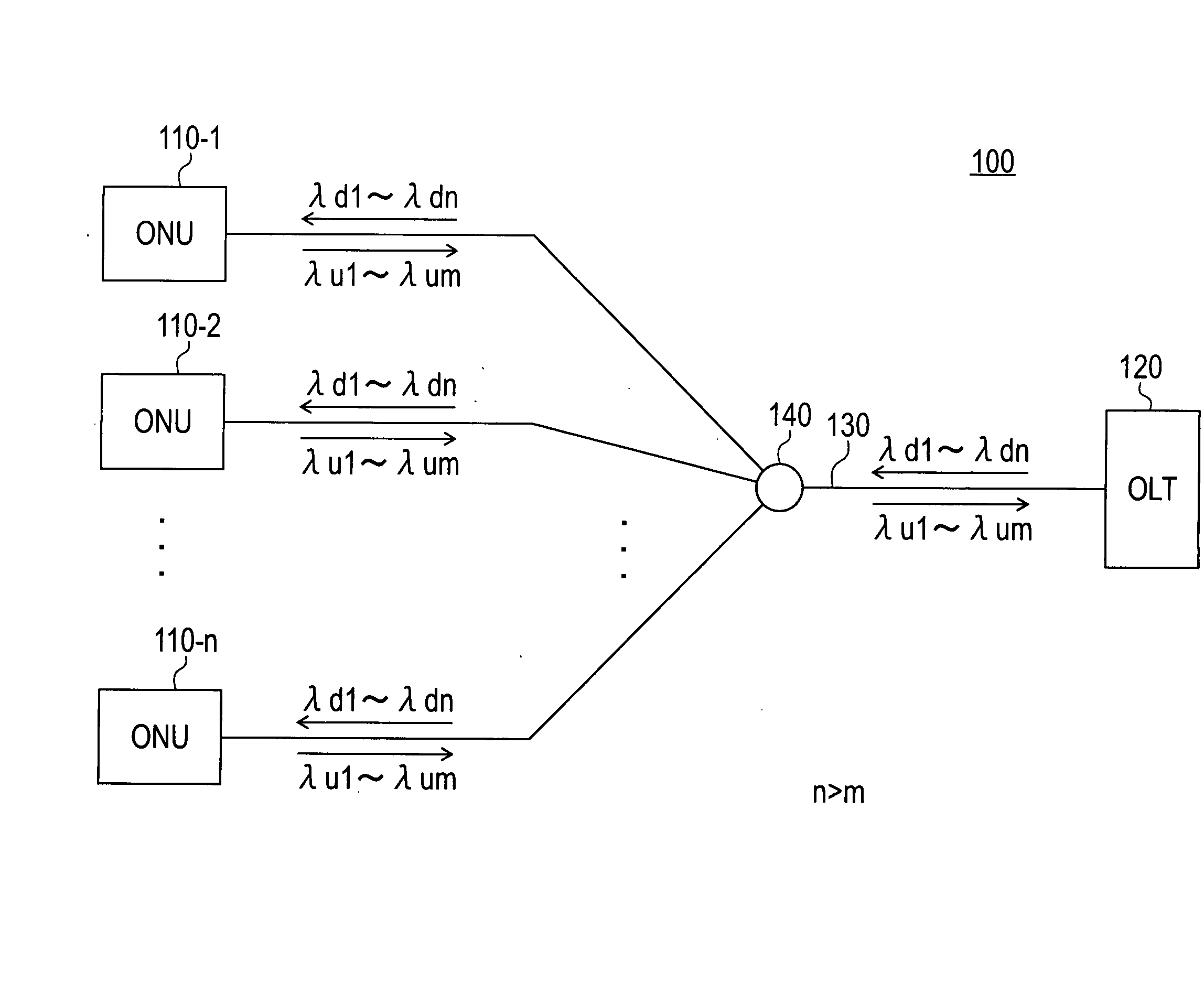
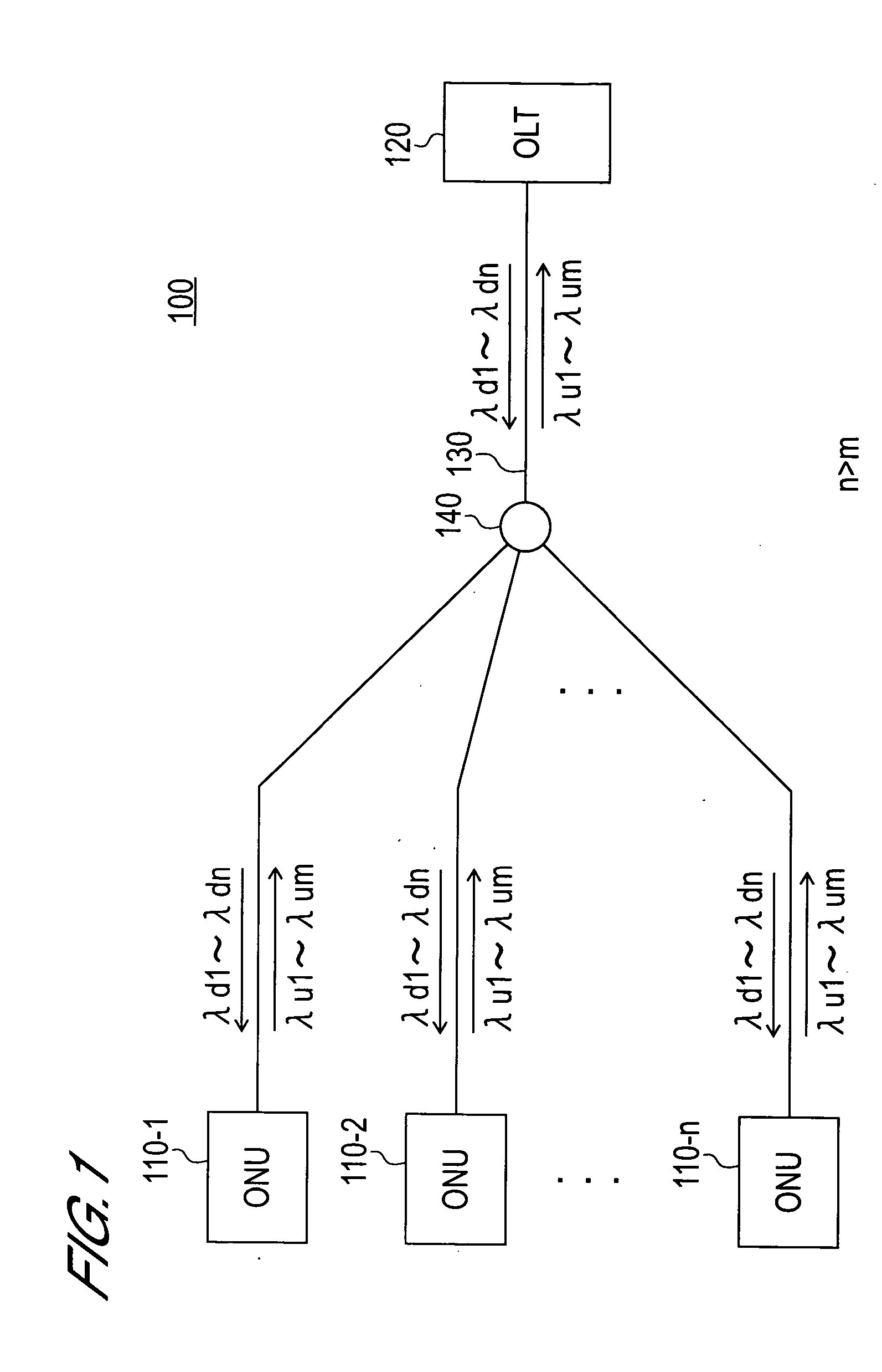
[0046]FIG. 1 is a diagram depicting a general configuration of the optical communication network according to the present embodiment. As FIG. 1 shows, the optical communication network 100 of the present embodiment has the PON structure, and comprises ONUs 110-1-110-n, OLT 120, optical fiber 130 and optical coupler 140.

[0047] The ONUs 110-1-110-n are subscriber side terminal devices of the optical commun...

second embodiment

[0080] The optical communication network according to the second embodiment of the present invention will now be described with reference to FIG. 8-FIG. 10.

[0081] In the present embodiment, the ONUs and the OLT are constructed such that each ONU can use a plurality of wavelengths simultaneously.

[0082] The general configuration of the optical communication network according to the present embodiment is the same as that of the first embodiment (see FIG. 1), so description thereof is omitted.

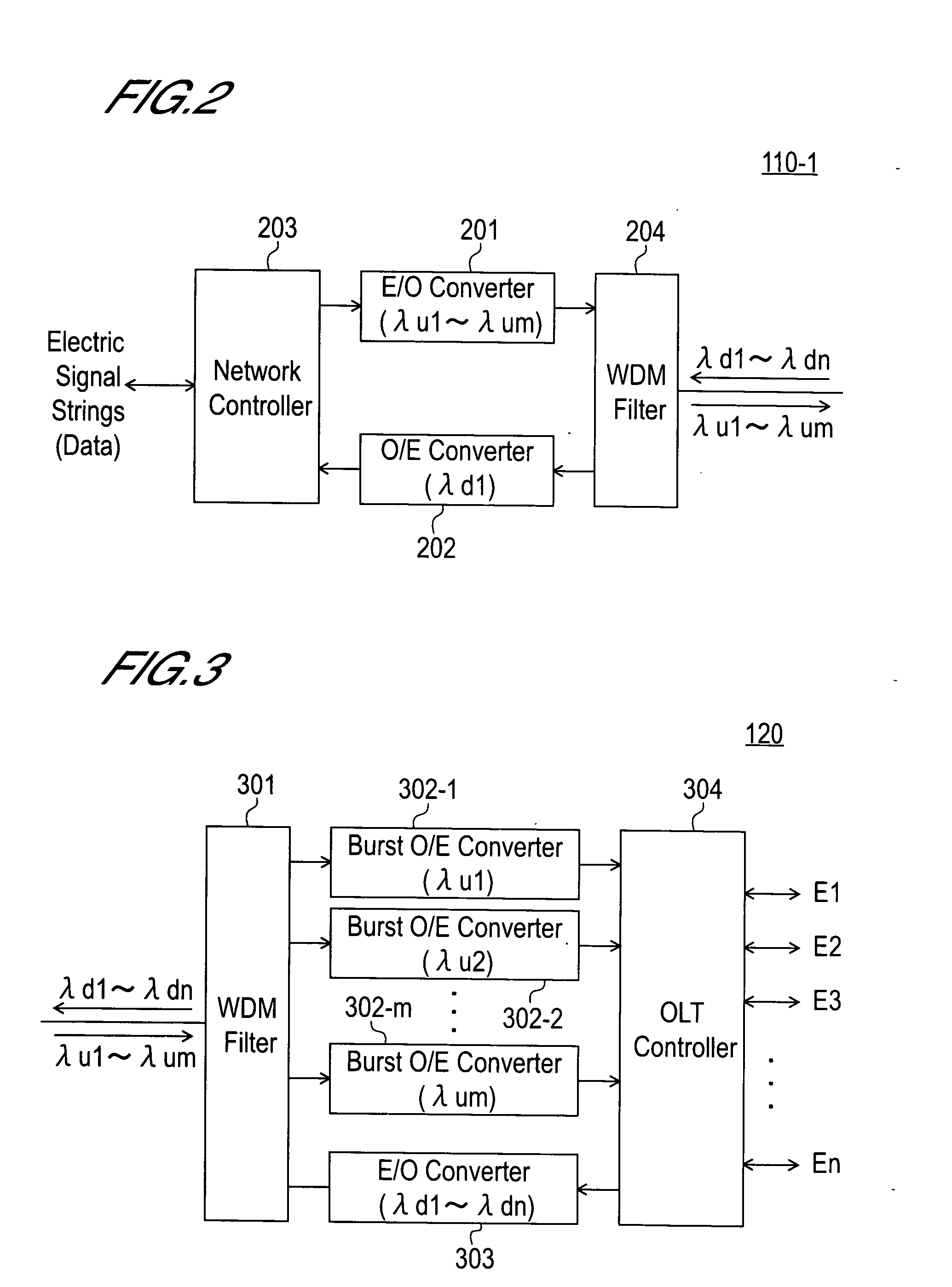
[0083]FIG. 8 is a block diagram depicting the internal configuration of the ONU according to the present embodiment. In FIG. 8, the composing elements denoted with the same reference symbols as FIG. 2 are the same as those in FIG. 2. As FIG. 8 shows, the ONU according to the present embodiment comprises the electric / optical converters 810-1-810-m and the switch 820.

[0084] The electric / optical converters 810-1-810-m have a fixed wavelength light source (not illustrated) which outputs light with ...

third embodiment

[0092] The optical communication network according to the third embodiment of the present invention will now be described with reference to FIG. 11 and FIG. 12.

[0093] In the present embodiment, a λ-TDMA system according to the present invention is applied to both the up and down directions.

[0094]FIG. 11 is a block diagram depicting the internal configuration of an ONU according to the present embodiment. As FIG. 11 shows, the ONU of the present embodiment comprises an electric / optical converter 1101, burst optical / electric converters 1102-1-1102-p, network controller 1103 and WDM filter 1104.

[0095] The electric / optical converter 1101 converts the electric signal strings into optical signal strings using the wavelength selective light source, which generates lights with m types of wavelengths λu1-λum, and outputs them to the WDM filter 1104. The optical wavelength and the output timing of the optical signal strings generated by the electric / optical converter 1101 are controlled by...


PUM


Abstract

An optical communication network using a communication system which is combined optical time-division multiplexing and optical wavelength-division multiplexing. The electric / optical converter converts an electric signal strings, which are input from the outside, into optical burst signals by selectively using a plurality of types of optical wavelengths. The network controller controls the optical wavelength selected by the electric / optical converter and the output timing of the optical burst signals for each one of the optical burst signals so that the optical burst signals received by the OLT are time-division multiplexed and wavelength-division multiplexed. By combining optical time-division multiplexing and optical wavelength-division multiplexing, an optical communication network of which the transmission band is wider than a TDMA system can be provided with a lower cost and lower facility scale than a WDM system.

Description

BACKGROUND OF THE INVENTION [0001] 1. Field of the Invention [0002] The present invention relates to a PON (Passive Optical Network) type optical communication network, and more particularly to an optical communication network using a communication system combining optical time division multiplexing and optical wave division multiplexing systems. [0003] 2. Description of Related Art [0004] As an optical communication network, PON, for example, is known. PON is a system for sharing one optical fiber by a plurality of subscribers (that is, homes which join the service) by branching an optical communication path by a coupler. PON is used by such a service as FTTH (Fiber To The Home). As an optical communication network based on PON, GE (Gigabit Either)-PON, A (Asynchronous transfer mode)-PON, B (Broadband)-PON, G (Gigabit)-PON, WDM (Wavelength Division Multiplexed)-PON and DWA (Dynamic Wavelength Allocation)-PON, for instance, are known. Here, GE-PON is standardized as IEEE 802.3ah, A-...

Claims


Application Information

Patent Timeline
Patent Type & Authority Applications(United States)
IPC IPC(8): H04J14/00H04B10/27H04B10/272H04B10/524H04B10/572H04J3/00H04J14/02H04J14/08
CPCH04J14/0226H04J14/0227H04J14/0282H04J14/086H04Q11/0067H04Q2011/0016H04J14/0247H04J14/0252
Inventor ISHIMURA, KATSUHIRO
Owner OKI ELECTRIC IND CO LTD
Why Eureka
Try Eureka