
Resource utilization efficiency during hand-off in mobile communication systems

a mobile communication system and resource utilization efficiency technology, applied in the field of wireless communication systems, can solve the problems of data packet loss, data throughput drop, missing or delayed acknowledgment signals, etc., and achieve the effect of avoiding disadvantages and maintaining data throughpu

Inactive Publication Date: 2006-06-08
WRIGHT DALE E +1
View PDF17 Cites 13 Cited by
  • Summary
  • Abstract
  • Description
  • Claims
  • Application Information

AI Technical Summary

Benefits of technology

This approach ensures efficient use of network resources, reduces the likelihood of data packet loss, and maintains data throughput during handoffs by routing packets directly to the involved base stations, making additional base station resources available for other users.

Problems solved by technology

Any discontinuities in the wireless data path as a result of a handoff can cause data packet loss, which results in missing or delayed acknowledgment signals between the end user machine and the server.
This increases the likelihood that the applicable TCP protocols at either end of the network connection will invoke congestion avoidance / slow start modes at the server, leading to a drop in data throughput in the system.
While multicasting arrangements of this type can decrease the probability of lost packets to help maintain throughput in the system during handoff, they do not use the resources of the cellular system in an efficient way.
The expensive facilities of all the other base stations in the group that are pressed into service in expectation of this particular handoff are unavailable for productive use elsewhere.
In addition, by multicasting identical packets to so many different base stations, the load on the network infrastructure is unnecessarily increased.

Method used


Image

  • Resource utilization efficiency during hand-off in mobile communication systems
  • Resource utilization efficiency during hand-off in mobile communication systems
  • Resource utilization efficiency during hand-off in mobile communication systems

Examples


Embodiment Construction

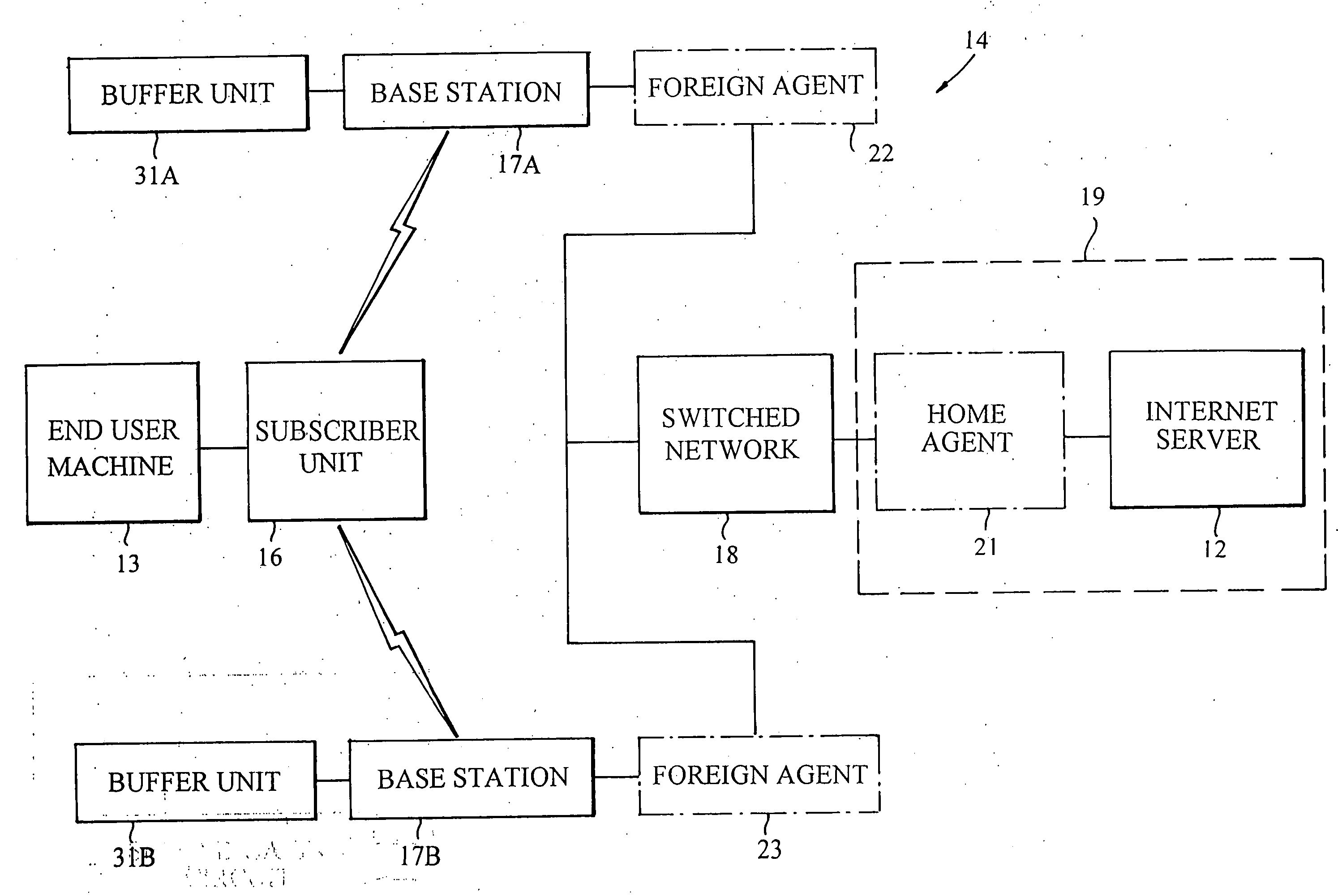
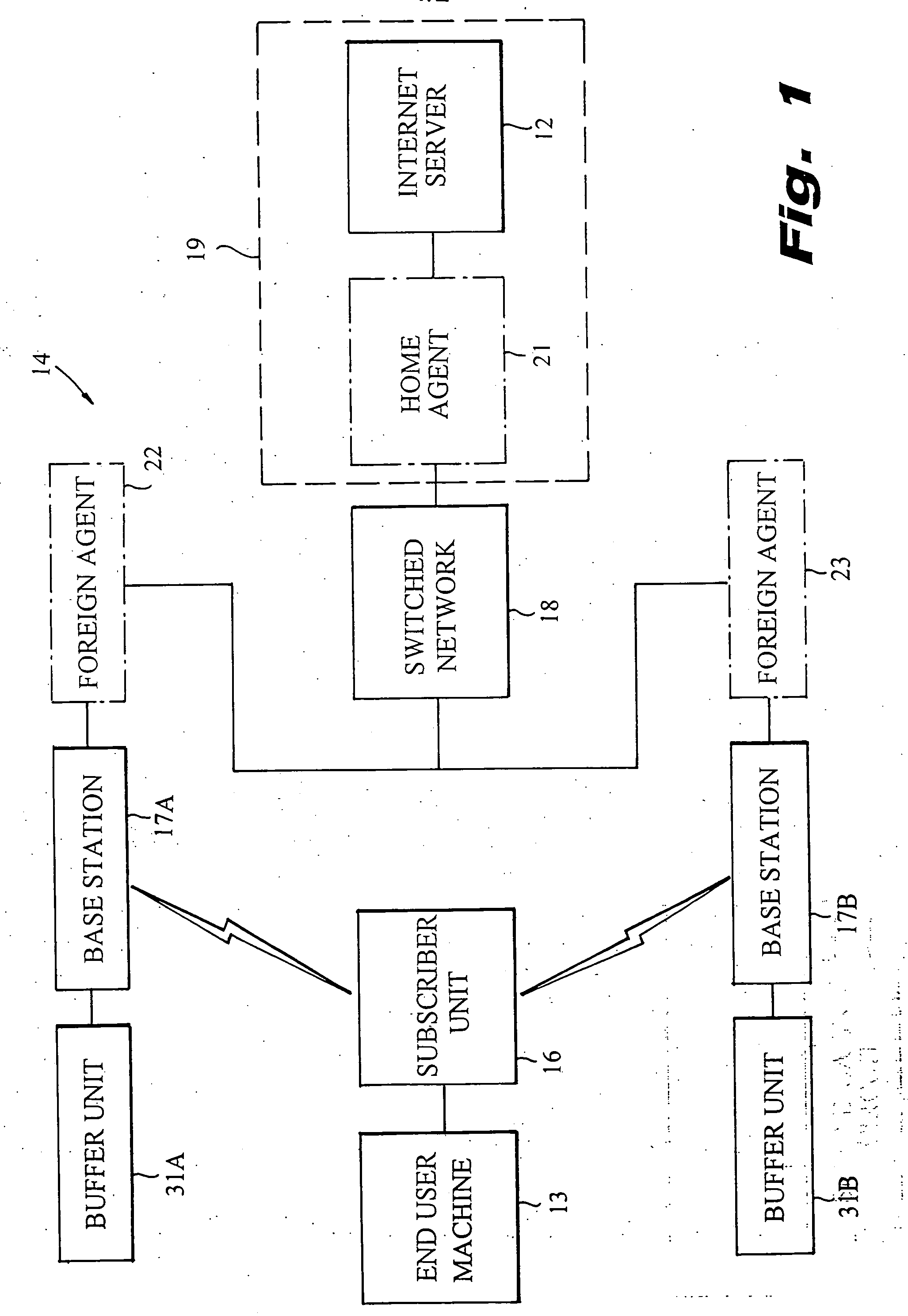
[0012] Referring to FIG. 1, there is depicted a wireless communication system 11, such as a cellular packet network, which illustratively operates according to the Mobile IP protocol. The system 11 is adapted for the two-way transmission of digital data packets between an Internet server 12 and an end user machine 13. The end user machine 13 may be a laptop computer, a portable computer, a personal digital assistant (PDA), or the like, which may be moved from place to place.

[0013] The system 11 has a wireless link 14 that includes a mobile subscriber unit 16 and a multiplicity of base stations 17, two of which (identified as 17A and 17B) are illustrated. The subscriber unit 16 is coupled to the end user machine 13. The base stations 17A and 17B are connected to the server 12 through a switched network 18, illustratively the Internet. Data packets transmitted from the server 12 to the end user machine 13 are routed through the switched network 18, a selected one of the base stations...


PUM


Abstract

An improved method of maintaining data throughput during handoff in a wireless communication link operating with the Mobile IP protocol is described. A first base station initially servicing a mobile subscriber unit is associated with a first Mobile IP foreign agent that is registered with the Mobile IP home agent as a first mobility binding between the subscriber unit and the home agent. When the subscriber unit issues a request to be handed off from the first base station to a second base station, a second foreign agent associated with the second base station is registered with the home agent as a simultaneous binding with the first mobility binding between the subscriber unit and the home agent. This permits both foreign agents to simultaneously receive a sequence of data packets from the home agent. Before handoff is executed, the data packet sequence routed to the second foreign agent is stored at the second base station. After handoff is complete, such stored packets are forwarded to the subscriber unit starting with a predetermined numbered packet in the stored sequence, and the first foreign agent is de-registered with the home agent.

Description

RELATED APPLICATION [0001] This application is a continuation of application Ser. No. 09 / 802,128, filed on Mar. 8, 2001. The entire teachings of the above application are incorporated herein by reference.BACKGROUND OF THE INVENTION [0002] This invention relates to wireless communication systems, such as cellular packet networks, and more particularly to methods of and apparatus for improving efficiency in such systems during handoff. [0003] In wireless communication systems for the transmission of data packets from a sending machine such as an Internet server, the switching or “handoff” of a mobile subscriber unit from one cellular base station to another is implemented as the subscriber unit moves between areas of different signal strength. Any discontinuities in the wireless data path as a result of a handoff can cause data packet loss, which results in missing or delayed acknowledgment signals between the end user machine and the server. This is true whether packets are destined ...

Claims


Application Information

Patent Timeline
Patent Type & Authority Applications(United States)
IPC IPC(8): H04Q7/00H04W36/00H04W36/02H04W80/04
CPCH04W36/0011H04W36/02H04W80/04H04W36/0019
Inventor WRIGHT, DALE E.HELLER, HOWARD
Owner WRIGHT DALE E
Learn More