Magnetic disk drive with adjustment of rotational balance

a magnetic disk drive and rotational balance technology, applied in the field of magnetic disk drives, can solve the problems of limiting the accuracy of machining parts for attaching to the spindle motor, difficult to suppress appropriately, and difficult to adopt the arrangement of placing screws in compact disk drives, so as to prevent the generation of dust and dirt, reduce the size and depth of the hole, and prevent the effect of loosening

Inactive Publication Date: 2006-06-08
WESTERN DIGITAL TECH INC
View PDF3 Cites 4 Cited by
  • Summary
  • Abstract
  • Description
  • Claims
  • Application Information

AI Technical Summary

Benefits of technology

[0007] It is therefore a feature of the present invention to provide a magnetic disk drive having a stable structure featuring the following. Specifically, the structure can be mounted in a narrow space in a compact magnetic disk drive. The structure suppresses generation of dust and dirt. The structure can reduce self-oscillation more easily than by improving assembly accuracy. The structure is further stable during high-speed spinning.
[0009] According to the present invention, the counterweight is formed of an elastic material and designed to be press-fitted into a hole. The diameter and depth of the hole can therefore be kept small. Looseness in the hole can also be prevented. Accordingly, space saving and prevention of generation of dust and dirt can be appropriately achieved. Further, the protruded portion provided on the side of the counterweight is designed to be slid into the gap between the clamp board and the motor hub. The counterweight is therefore stably held in position in the hole, opposing to a large acceleration during high-speed spinning.

Problems solved by technology

There is a limit to existing accuracy in machining parts for attaching to the spindle motor, and in assembling these parts together.
It is difficult to suppress appropriately, by improving this accuracy, the self-oscillation occurring in conjunction with the recent effort made to increase the rotating speed in the 2.5-inch disk drive.
Further, it is difficult to adopt the arrangement of placing the screw in a compact disk drive, in which downsizing is at a premium, for the following reason.
Moreover, there is a problem that fastening the screw involves generation of dust and dirt.
On the other hand, the arrangement, in which the plastic pin is fitted into a hole, presents a problem, in which looseness occurs in the hole into which the pin is driven, causing dust and dirt to be generated.

Method used


Image

  • Magnetic disk drive with adjustment of rotational balance
  • Magnetic disk drive with adjustment of rotational balance
  • Magnetic disk drive with adjustment of rotational balance

Examples


Embodiment Construction

[0016] An exemplary embodiment (hereinafter referred to as the “embodiment”) of the present invention will be described in detail with reference to the accompanying drawings.

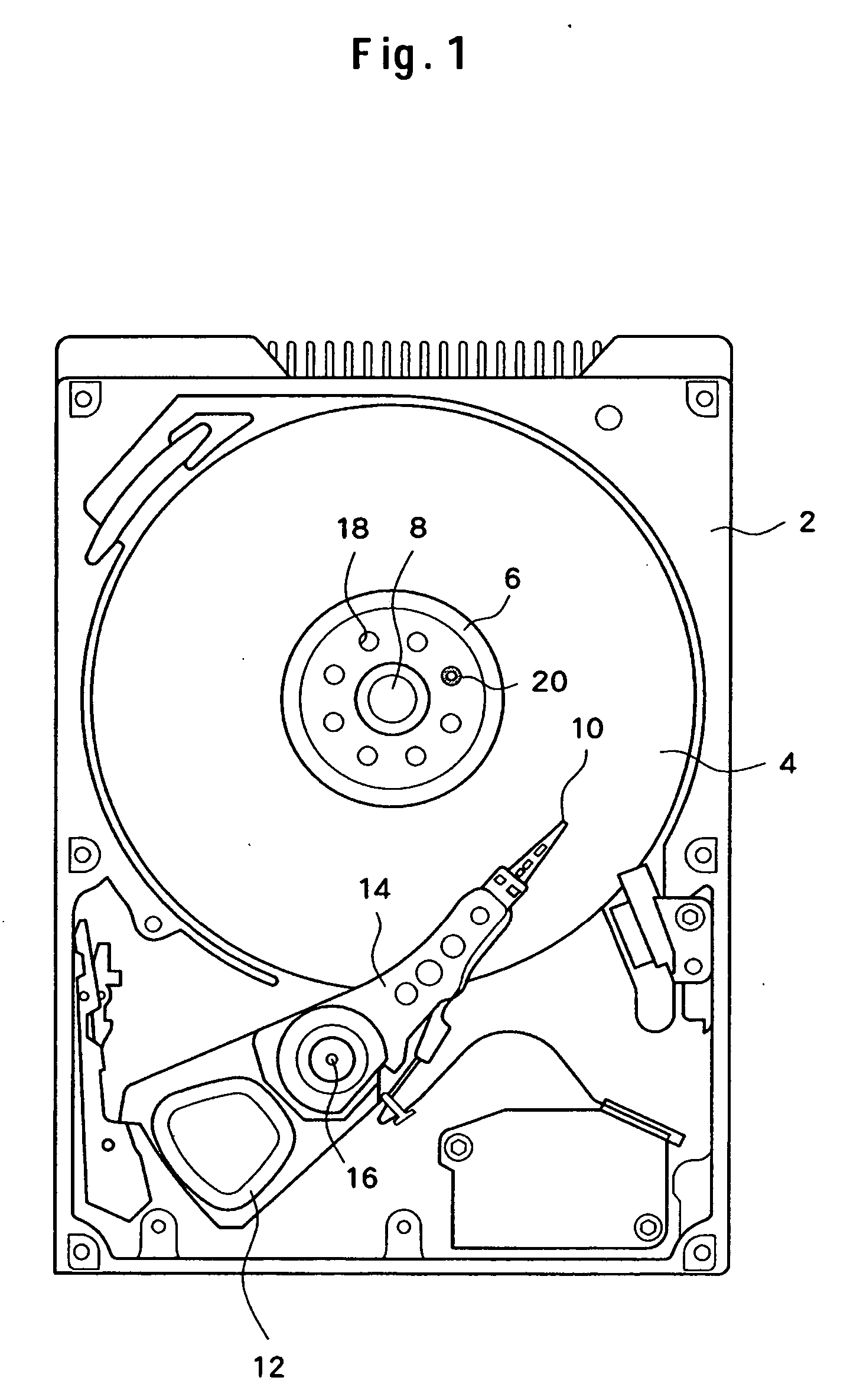
[0017]FIG. 1 is a plan view showing schematically a 2.5-inch magnetic disk drive according to the embodiment of the present invention. The magnetic disk drive includes a magnetic disk 4 in a cabinet 2. The magnetic disk 4 is clamped between a hub of a spindle motor and a clamp (clamp plate) 6. The magnetic disk 4 is spun at high speed around a rotary axis 8 by the spindle motor. For example, in the magnetic disk drive according to the embodiment of the present invention, the magnetic disk 4 can be spun at about 7500 rpm. The spindle motor is hidden behind the clamp 6 and not visible in FIG. 1. The magnetic disk 4 includes concentrically formed tracks. A magnetic head 10 is held in close proximity to a surface of the magnetic disk 4, performing read / write operations along the track. The position of the magnetic ...


PUM

PropertyMeasurementUnit
specific gravityaaaaaaaaaa
circumferenceaaaaaaaaaa
shapeaaaaaaaaaa

Abstract

Embodiments of the invention provide, in a compact magnetic disk drive, a stable structure capable of reducing self-oscillation occurring from disk spinning, while suppressing generation of dust and dirt. In one embodiment, a magnetic disk is mounted on a hub of a spindle motor. A clamp is further attached to secure the magnetic disk in position. A plurality of opening portions are formed in the clamp around an axis. A counterweight formed of an elastic material is mounted in the opening portion by being press-fitted therein. The counterweight is less likely to generate dust and dirt through friction during insertion and looseness. A gap is provided between the clamp and the hub at locations near the opening portions. The counterweight has a protruded portion on a side surface of a circular column portion. The protruded portion slides into the gap between the clamp and the hub, counteracting a tendency of the counterweight to drop out of position.

Description

CROSS-REFERENCES TO RELATED APPLICATIONS [0001] This application claims priority from Japanese Patent Application No. JP2004-354078, filed Dec. 7, 2004, the entire disclosure of which is incorporated herein by reference. BACKGROUND OF THE INVENTION [0002] The present invention relates generally to a magnetic disk drive and, more particularly, to an adjustment of a rotational balance after assembly of a disk assembly. [0003] In recent years, efforts are being made to achieve a higher rotating speed of the disk in order to meet the need for an improved access performance in a 2.5-inch disk drive. Self-oscillation is involved here of the magnetic disk, arising from imbalance of a spindle motor itself or imbalance caused by eccentricity of different members of the magnetic disk after assembly. The self-oscillation tends to increase in proportion to the rotating speed of the disk to the second power. The effort made to increase the disk rotating speed in the 2.5-inch disk drive could mak...

Claims


Application Information

Patent Timeline
Patent Type & Authority Applications(United States)
IPC IPC(8): G11B17/02
CPCG11B17/02G11B17/038
Inventor HIRAMATSU, TOMOKIOKADA, TAKAHISASUMIYA, TAKEJITSUJINO, HITOSHI
Owner WESTERN DIGITAL TECH INC
Why Eureka
Try Eureka