
Amplifier gain and phase stabilizer

a phase stabilizer and amplifier technology, applied in the field of satellite-based communications systems, can solve the problems of loss of output power, loss of localized signal path, poor quality reception or even total loss of signal to an end user,

Inactive Publication Date: 2006-06-01
THE BOEING CO
View PDF5 Cites 10 Cited by
  • Summary
  • Abstract
  • Description
  • Claims
  • Application Information

AI Technical Summary

Benefits of technology

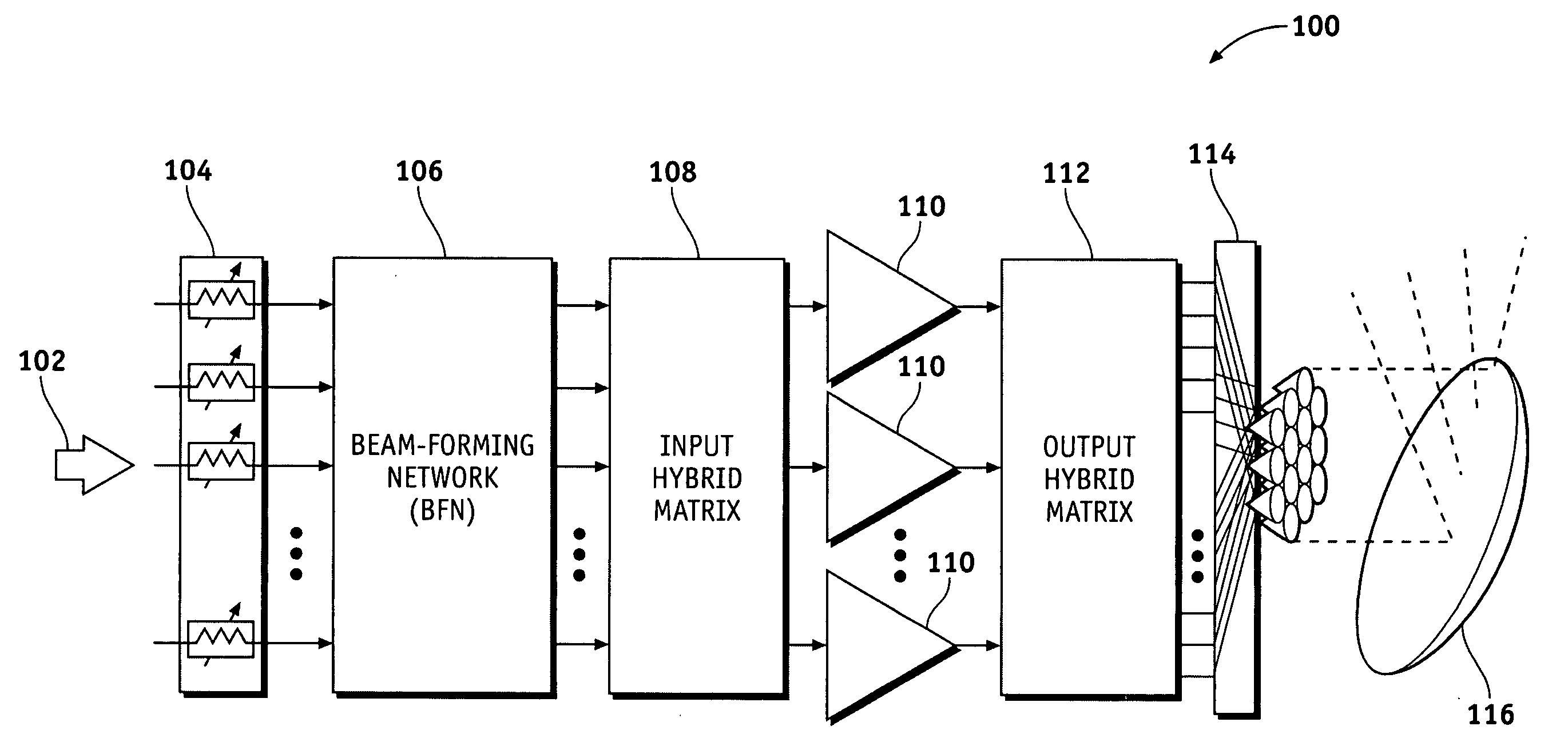
The patent describes devices and methods for stabilizing the phase and gain parameters of an amplifier used in a satellite transmitter power pooling arrangement. The method involves using a pilot signal with a reference carrier and a reference sideband signal. This pilot signal is introduced into the amplifier and a sample of the amplified pilot signal is mixed with the reference carrier to extract the sideband signal. The sideband signal is then divided into two signals, which are converted into a phase control signal and a gain control signal. These control signals are fed back to the amplifier input circuit to modify the phase and amplitude of the input signal to compensate for changes in phase and gain parameters within the amplifier. The technical effect of this patent is to provide a way to stabilize the performance of the amplifier and ensure consistent output quality.

Problems solved by technology

One obstacle in achieving ideal EIRP coverage, however, is the adverse effect of localized signal path losses that are typically caused by weather-related conditions such as rain.
That is, rain can attenuate transmitted signal strength to a degree that may result in poor quality reception or even a total loss of signal to an end user.
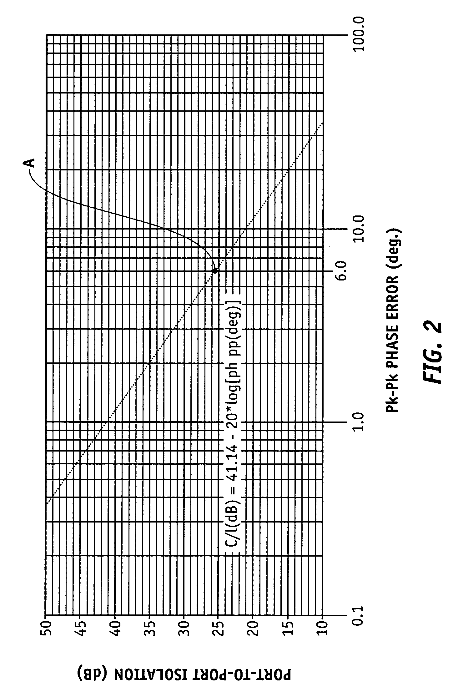
However, if these gain and phase parameters are not held constant, cross talk can occur between the output ports, and a loss of output power may result.
The stability of the amplifier gain and phase parameters can be adversely affected by influences such as changes in temperature, aging of associated internal and external components, power supply voltage drift, and so forth.
In addition, the phase and gain parameters of the line lengths between the amplifiers and the hybrid matrices can also affect the performance of the power pooling arrangement.

Method used


Image

  • Amplifier gain and phase stabilizer
  • Amplifier gain and phase stabilizer
  • Amplifier gain and phase stabilizer

Examples


Embodiment Construction

[0012] The following detailed description is merely exemplary in nature and is not intended to limit the invention or the application and uses of the invention. Furthermore, there is no intention to be bound by any expressed or implied theory presented in the preceding technical field, background, brief summary or the following detailed description.

[0013] Various embodiments of the present invention pertain to the area of satellite communications where a satellite transmitter sub-system utilizes a multi-amplifier power pooling arrangement for individual power adjustment to the respective feed horns. Unless all the amplifiers in such an arrangement have essentially identical phase and gain characteristics, cross talk and power losses can occur at the output ports, thus reducing the efficiency of the transmitter sub-system. To overcome this problem, a phase and gain stabilization network is disclosed herein that operates to maintain essentially constant and identical phase and gain c...


PUM


Abstract

Methods and apparatus are provided for stabilizing the phase and gain of an amplifier in a power pooling arrangement. A pilot signal combining a reference carrier frequency with a reference sideband frequency is passed through the amplifier via an adjustable phase shifter and an adjustable attenuator in the amplifier input line. A portion of the amplified pilot signal is coupled from the output of the amplifier and mixed with the reference frequency. The remaining audio frequency signal is compared to a reference (input) audio signal to determine phase and gain changes during amplification in the amplifier. Phase and gain control signals are developed from this comparison, and are fed back to the adjustable phase shifter and adjustable attenuator, respectively, in order to compensate an incoming signal for phase and gain variations in the amplifier.

Description

TECHNICAL FIELD [0001] The present invention generally relates to satellite-based communications systems, and more particularly relates to the stabilization of the gain and phase characteristics of amplifiers used for satellite transmissions. BACKGROUND [0002] Satellite-based communication systems are typically used to provide TV broadcast transmissions as well as other types of communication signals over a large geographical area, such as the contiguous 48 states of the U.S. In a typical satellite-based communication system, the satellite receives signals from a feeder Earth station and then re-transmits the signals to end user stations throughout a target area. Ideally, the satellite transmissions are intended to deliver an equitable level of signal power, known as the effective isotropic radiated power (EIRP), to every end user station within the satellite coverage area. One obstacle in achieving ideal EIRP coverage, however, is the adverse effect of localized signal path losses ...

Claims


Application Information

Patent Timeline
Patent Type & Authority Applications(United States)
IPC IPC(8): H04B1/04
CPCH03F1/0205H03F1/32H03F1/3282H03F3/211H03F3/24H03F3/602H03F3/604H04B7/18515H03F1/30H03F3/58H03G3/005H03G9/04
Inventor ROSEN, HAROLD A.THOMPSON, JAMES D.
Owner THE BOEING CO
Learn More