Method of optical element and objective lens

a technology of optical elements and objective lenses, applied in the field of optical element design methods, can solve the problems of inability to correct function, limited degree of freedom for design of diffracting structures, and inability to achieve correct function, etc., and achieve the highest recording density, high light usage efficiency, and excellent compatibility

Active Publication Date: 2006-06-01
KONICA MINOLTA INC
View PDF14 Cites 23 Cited by
  • Summary
  • Abstract
  • Description
  • Claims
  • Application Information

AI Technical Summary

Benefits of technology

[0020] Still optionally, by the first diffraction function, the diffracting structure may generate an aberration having a direction in which each of the spherical aberration caused when the first optical disc is used and the spherical aberration caused when the second optical disc is used is corrected. By the second diffraction function, the diffracting structure may decrease change of the spherical aberration caused by the wavelength shift in which a wavelength of the first light beam shifts from the first design wavelength when the first optical disc is used.
[0034] With this configuration, it becomes possible to secure a considerably high usage efficiency of light for the first light beam in a recording operation and / or a reproducing operation for the first optical disc having the highest recording density.

Problems solved by technology

The degrees of freedom for design of a diffracting structure are limited.
Therefore, it was assumed that if a diffracting structure is formed to support the two types of optical discs, giving additionally a correcting function for a wavelength shift (i.e., a function of correcting change of a spherical aberration caused by a wavelength shift in each of two different light beams for the two types of optical discs) to the diffracting structure is impossible.
However, the degrees of freedom of design of a diffracting structure are limited.
However, if the optical system is configured to have the diffracting structures on two lens surfaces as proposed in the above mentioned article, the possibility that the optical performance deteriorates due to a manufacturing error, such as decentering, may increase.
In this case, one of the surfaces of the objective lens (i.e., one of the diffracting structures) is exposed to the outside through a disc tray, by which the possibility that the diffracting structure exposed-to the outside is damaged when a lens cleaner is used increases.

Method used


Image

  • Method of optical element and objective lens
  • Method of optical element and objective lens
  • Method of optical element and objective lens

Examples


first embodiment

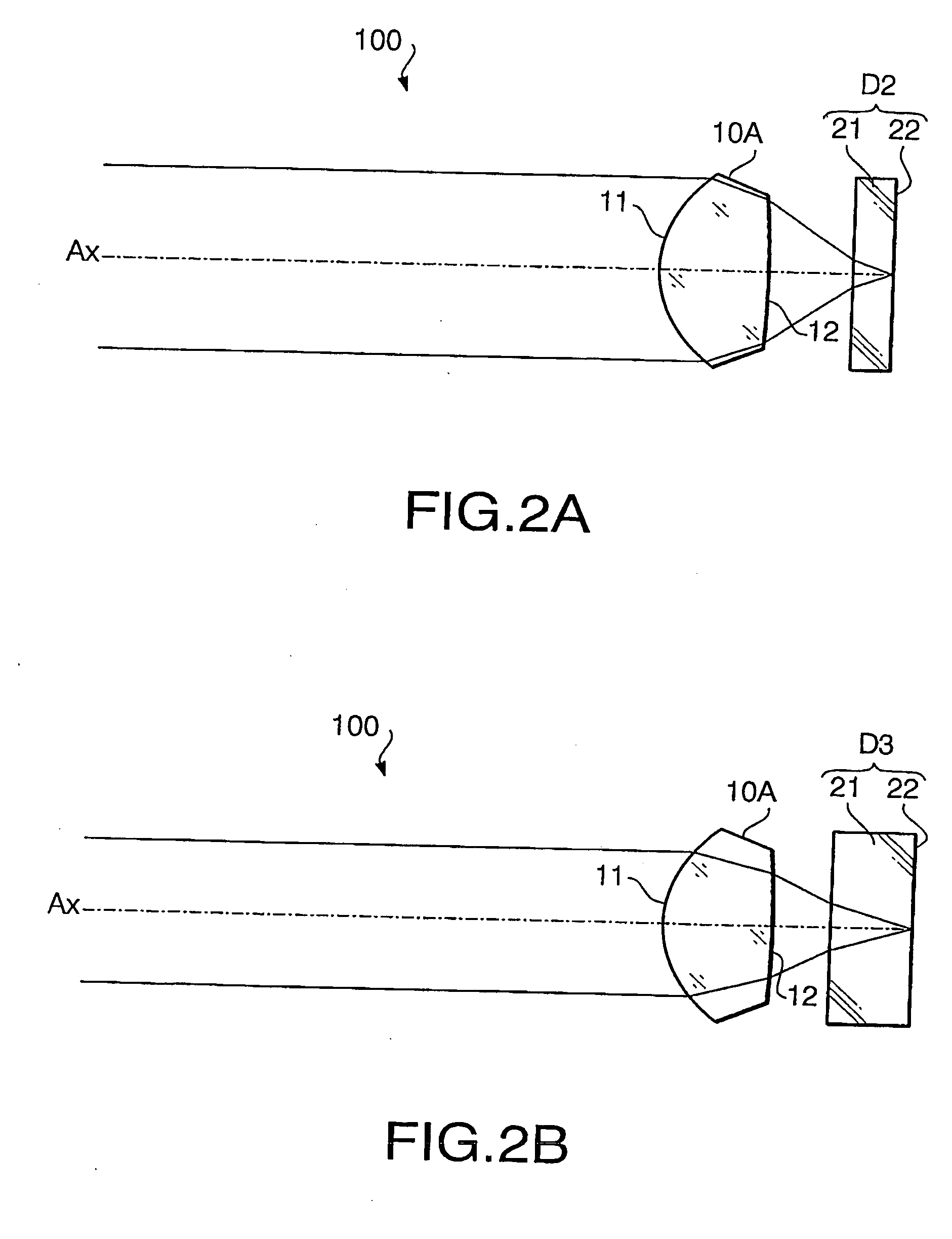
[0160] Hereafter, a design method according to a first embodiment and an objective lens 10A formed according to the design method will be described. The objective lens 10A can be used for two types of optical discs (i.e., the objective lens 10A has compatibility for the two types of optical discs). In this embodiment, the objective lens 10A is configured to support the optical discs D2 and D3. However, an objective lens of a different type having compatibility for another pair of optical discs may be designed by the design method according to the first embodiment.

[0161]FIG. 1 shows a general configuration of an optical disc drive (an optical system) 100 according to the first embodiment. The optical disc drive 100 includes a light source 2A emitting the second laser beam for the optical disc D2, a light source 3A emitting the third laser beam for the optical disc D3, coupling lenses 2B and 3B, a beam splitter 41, a half mirror 43, a light receiving unit (sensor) 44 and the objectiv...

second embodiment

[0203] Hereafter, a design method according to a second embodiment and an objective lens 10B formed by the design method according to the second embodiment will be described. The objective lens 10B is able to support three types of optical discs (i.e., the objective lens 10B has compatibility for the three types of optical discs). In this embodiment, the objective lens 10B is configured to support the optical discs D1, D2 and D3. In FIG. 4 (and in the following drawings), to elements which are equivalent to those of the first embodiment, the same reference numbers are assigned, and explanations thereof will not be repeated.

[0204]FIG. 4 shows a general configuration of an optical disc drive (an optical system) 200 according to the second embodiment. The optical disc drive 200 includes a light source 1A emitting a first laser beam for the optical disc D1, the light source 2A emitting the second laser beam for the optical disc D2, the light source 3A emitting the third laser beam for ...

third embodiment

[0213] Hereafter, a design method according to a third embodiment and an objective lens 10C (see FIG. 4) formed by the design method according to the third embodiment will be described. The objective lens 10C is able to support three types of optical discs (i.e., the objective lens 10C has compatibility for the three types of optical discs), and to cancel the spherical aberration which varies depending on the wavelength shift caused when each of the optical discs D1, D2 and D3 is used. That is, a diffracting structure formed on the objective lens 10C has both the three wavelength compatibility function and the wavelength shift compensation function. Since the configuration of the optical disc drive 200 shown in FIGS. 4, 5A, 5B and 5C is also applied to an optical disc drive according to the third embodiment, the configuration of the optical disc drive according the third embodiment will be explained with reference to FIGS. 4, 5A, 5B and 5C.

[0214] Hereafter, the design method of des...


PUM

PropertyMeasurementUnit
wavelengthaaaaaaaaaa
thicknessaaaaaaaaaa

Abstract

A method of designing an optical element to be used for an optical system in which each of a plurality of light beams having different design wavelengths passes through the optical element is provided. The method includes determining at least two types of optical path difference functions including first and second optical path difference functions in such a manner that proportion, brought by the first optical path difference function, between diffraction orders at which diffraction efficiencies of the plurality of light beams are maximized is different from proportion, brought by the second optical path difference function, between diffraction orders at which diffraction efficiencies of the plurality of light beams are maximized, and obtaining a shape defined by combining the at least two types of optical path difference functions so as to apply the obtained shape to at least one surface of surfaces of the optical element.

Description

BACKGROUND OF THE INVENTION [0001] The present invention relates to a design method of an optical element, such as an objective lens, used for an optical disc drive capable of recording data to and / or reproducing data from a plurality of types of optical discs based on different standards. [0002] There are various types of optical discs on which digital information is recorded at various densities, respectively. For example, a DVD (digital versatile disc) has a recording density higher than that of a CD (compact disc) or a CD-R (CD Recordable) and has a cover layer thinner than that of the CD or CD-R. [0003] Recently, new technical standards for optical discs, such as an HD DVD (High Definition DVD) and a BD (Blu-ray Disc), having further higher recording densities have been proposed. Such a new standard optical disc has a thickness of a cover layer smaller than or equal to that of the DVD. Under these circumstances, optical disc drives (i.e., optical systems in the optical disc dri...

Claims


Application Information

Patent Timeline
Patent Type & Authority Applications(United States)
IPC IPC(8): G11B7/00G11B7/135
CPCG02B27/42G02B27/4238G02B27/4294G11B7/1367G11B7/1374G11B7/13922G11B2007/0006G02B5/18G02B13/00G11B7/1353
Inventor MARUYAMA, KOICHITASHIRO, YOSHIYUKIKOREEDA, DAISUKE
Owner KONICA MINOLTA INC
Why Eureka
Try Eureka