
Multiple-ccfl parallel driving circuit and the associated current balancing control method for liquid crystal display

a liquid crystal display and driving circuit technology, applied in the direction of electric variable regulation, process and machine control, instruments, etc., can solve the problems of affecting the performance of current balance, the impedance of storage energy components cannot be precisely controlled, and the single ccfl in the backlight module becomes less and less able to provide enough backlight, etc., to achieve the effect of improving the uniformity of the image of a large-siz

Inactive Publication Date: 2006-06-01
HSIU YING LI +3
View PDF6 Cites 14 Cited by
  • Summary
  • Abstract
  • Description
  • Claims
  • Application Information

AI Technical Summary

Benefits of technology

"The present invention provides a multiple-CCFL parallel driving circuit and the associated current balancing control method for LCD. The circuit uses a current mirror technique to equalize the driving current of CCFLs and achieve current balance among them, which improves the uniformity of the image of a large-size LCD. The circuit includes a half-bridge resonant inverter, a dc power supply, and multiple sets of CCFLs connected to a multiple-CCFL current balancing circuit. The current mirror circuit can be comprised of BJTs, JFETs, or MOSFETs. The technical effect of this invention is to improve the image quality of LCDs by achieving current balance among multiple CCFLs."

Problems solved by technology

However, as the size of LCDs becomes larger and larger, a single CCFL in the backlight module becomes less and less able to provide enough backlight.
However, the impedance of the storage energy components cannot be precisely controlled and the temperature of the storage energy components increases after it has been operating for a long period of time, thereby affecting the performance of current balance.
The effect of natural emitting heat is not good because the backlight module is enclosed in the inner space of the LCD.
After a long period of operation, it cannot keep the multiple CCFLs on current balance status.
Because this circuit is comprised of magnetic components and impedance components, the performance of the current balance is also affected by temperature.
This is a disadvantage when designing a light and thin LCD of a large size.
Because the impedances of the CCFLs are different from each other in the steady state, this circuit does not balance the driving current for a plurality of CCFLs.
However, the CCFLs operate under high voltage and as such this circuit needs to be concerned about anti-high voltage to prevent the component being damaged.
However, it increases the costs and the size of the circuit.

Method used


Image

  • Multiple-ccfl parallel driving circuit and the associated current balancing control method for liquid crystal display
  • Multiple-ccfl parallel driving circuit and the associated current balancing control method for liquid crystal display
  • Multiple-ccfl parallel driving circuit and the associated current balancing control method for liquid crystal display

Examples


first embodiment

[0032] Referring to FIG. 4, a multiple-CCFLs current balancing circuit with a basic current mirror structure 311 is shown. This is the multiple-CCFLs current balancing circuit. The connected points TC1, TC2, TC3, and TC4 to TCN are connected to a plurality of CCFLs. The multiple current balancing circuit with a basic current mirror structure 311 can be comprised of BJTs, JFETs or MOSFETs. It can achieve the result of the driving current balance of the multiple-CCFLs by the basic structure of the current mirror.

second embodiment

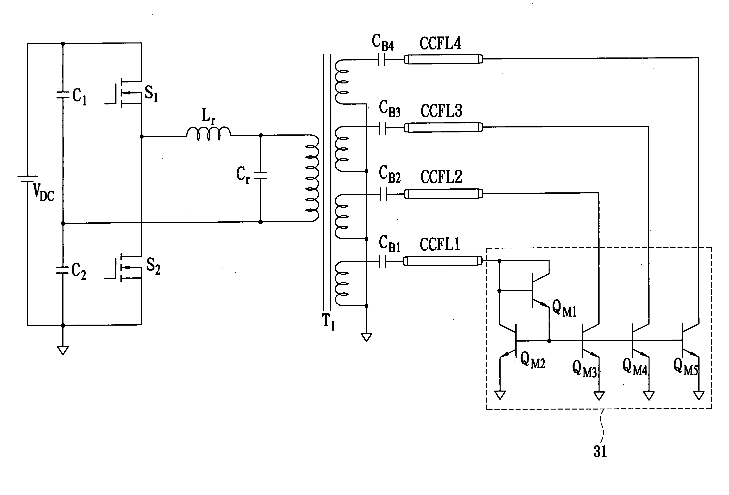
[0033] Referring to FIG. 5, a multiple CCFLs current balancing circuit with a current mirror structure for increasing output impedance of the current source 312 is shown. This is the multiple-CCFL current balancing circuit. The connected points TW1, TW2, TW3, and TW4 to TWN are connected to a plurality of CCFLs. This circuit connects the collector and the base of the BJT QW3 together. It increases the output impedance of the current source by a negative feedback method. Therefore, it can reduce the influence of any change in the impedance of the CCFLs which affects the multiple CCFLs current balancing circuit. The multiple current balancing circuit with a basic current mirror structure 312 can be comprised of BJTs, JFETs or MOSFETs.

third embodiment

[0034] Referring to FIG. 6, a multiple CCFLs current balancing circuit with a current mirror structure and proportional resistances 313 is shown. This is the multiple-CCFL current balancing circuit. The connected points TR1, TR2, TR3, and TR4 to TRN are connected to a plurality of CCFLs. The emitters of a plurality of BJT QR1, QR2, QR3, and QR4 to QRN are each connected to proportional resistances RR1, RR2, RR3, and RR4 to RRN. The multiple-CCFLs current balancing circuit can fine-tune the driving current of the CCFLs by adjusting the impedance values of the proportional resistances RR1, RR2, RR3, and RR4 to RN. It can precisely adjust the driving currents of the multiple-CCFLs by altering the impedance values of the proportional resistances, thereby balancing the current. The multiple current balancing circuit with a current mirror structure and proportional resistances 313 can be comprised of BJTs, JFETs or MOSFETs.

[0035] Referring to FIG. 7, a system diagram of the backlight syst...


PUM


Abstract

A multiple-CCFL parallel driving circuit and the associated current balancing control method for LCD are presented, wherein the circuit comprises a plurality of CCFLs for providing the backlight for a LCD; a boosting transformer with a plurality of outputs for providing the driving voltage and current for driving the plurality CCFLs; a plurality of ballast capacitors, the ballast capacitors connect between the boosting transformer and the CCFLs; and a multiple CCFL current balancing circuit. This invention uses a low cost current mirror circuit to equalize the driving current of a plurality of CCFLs and thus significantly improve the uniformity of the displayed image on a large-size LCD.

Description

BACKGROUND OF THE INVENTION [0001] 1. Field of the Invention [0002] The present invention relates to technology for a driving circuit and a method for cold cathode fluorescent lamp (CCFL) in the backlight modules of liquid crystal displays (LCDs). In particular, this invention provides a multiple-CCFL parallel driving circuit and the associated current balancing control method for LCD. [0003] 2. Description of the Related Art [0004] With the arriving of digital era as well as networks of information and entertainment available to millions worldwide, requesting for thin and flat panel display panels is undoubtedly an ongoing trend. In addition, features, such as larger size, better performance, and excellent uniformity of brightness, for display screens are increasingly demanded in consumer market. A LCD combined with CCFL, which works as backlight source, is so far the best choice in terms of the market requirements mentioned above. Besides, as a key component for driving light sour...

Claims


Application Information

Patent Timeline
Patent Type & Authority Applications(United States)
IPC IPC(8): G05F1/00
CPCH05B41/282H05B41/2827Y10S315/05Y10S315/02
Inventor LIN, CHANG-HUA
Owner HSIU YING LI
Learn More