Piezoelectric/electrostrictive device

a technology of electro-electrostrictive device and piezoelectric, which is applied in the direction of piezoelectric/electrostrictive/magneto-strictive device, piezoelectric/electrostrictive/magneto-strictive device, piezoelectric/electrostriction/magneto-strictive machine, etc., can solve the problems of material breakage, particle separation, inability to read/write data, etc., to achieve the effect of reducing

Inactive Publication Date: 2006-06-01
NGK INSULATORS LTD
View PDF6 Cites 10 Cited by
  • Summary
  • Abstract
  • Description
  • Claims
  • Application Information

AI Technical Summary

Benefits of technology

[0011] In view of the foregoing, an object of the present invention is to provide a piezoelectric / electrostrictive device which can be manufactured at high productivity and which enables effective prevention of particle separation from lateral end surfaces (worked surfaces) of a piezoelectric / electrostrictive layer constituting a piezoelectric / electrostrictive element.
[0015] This finishing of the rough surface through polishing (or a similar technique) reduces irregularities of the lateral end surface of the piezoelectric / electrostrictive layer to a very small level, whereby uniform residual strain (i.e., residual stress) occurs in the vicinity of the lateral end surface. Therefore, when, for example, the piezoelectric / electrostrictive layer is deformed during operation of the piezoelectric / electrostrictive device, the aforementioned local occurrence of abnormally high stress (stress concentration) in the vicinity of the lateral end surface is prevented, and thus particle separation tends not to occur.
[0017] Therefore, the piezoelectric / electrostrictive device which has undergone the aforementioned mechanical machining or the like is not required to be subjected to the above-described thermal treatment for elimination of microcracks in order to prevent particle separation from the lateral end surface of the piezoelectric / electrostrictive layer, the thermal treatment causing productivity reduction. In addition, the time required for the aforementioned mechanical machining or the like can be shortened, since polishing, etc. is performed after the mechanical machining or the like, and thus the size of irregularities of the rough surface formed by the mechanical machining or the like is not necessarily regulated to a relatively small level. In other words, the piezoelectric / electrostrictive device of the present invention can be readily manufactured within a relatively short period of time; i.e., the productivity of the device is high. That is, the piezoelectric / electrostrictive device provided by the present invention can be manufactured at high productivity, and enables effective prevention of particle separation from the lateral end surface (worked surface) of the piezoelectric / electrostrictive layer, which is a constituent of the piezoelectric / electrostrictive element.

Problems solved by technology

In the case where the above-disclosed piezoelectric / electrostrictive device is employed as, for example, an actuator for controlling the position of a magnetic head of a hard disk drive, adhesion of debris, dust, or the like onto the hard disk, etc., may cause incorrect reading / writing of data.
Such a fragile material of relatively low strength is likely to cause particle separation through, for example, application of repeated stress.
In general, particle separation from a cut surface of a material is caused by, for example, the following phenomenon: distribution of strain remaining in the vicinity of the cut surface after cutting (i.e., distribution of residual stress) becomes non-uniform due to large irregularities of the cut surface, and abnormally high stress (stress concentration) occurs locally in the vicinity of the cut surface upon deformation of the material, resulting in breakage of the material; or microcracks are generated in the vicinity of the cut surface of the material through application of load to the material during the course of cutting, and the microcracks grow through application of repeated stress to the material, resulting in breakage of the material.
However, such a cutting process involves a problem in that the process requires a considerably long period of time.
However, when such a predetermined thermal treatment is performed rapidly within a short period of time, or performed at an inappropriate temperature, thermal strain may occur in the piezoelectric / electrostrictive device, leading to reduction in the dimensional accuracy of the device.
Therefore, such a predetermined thermal treatment must be performed over a relatively long period of time under strict temperature control.

Method used


Image

  • Piezoelectric/electrostrictive device
  • Piezoelectric/electrostrictive device
  • Piezoelectric/electrostrictive device

Examples


Embodiment Construction

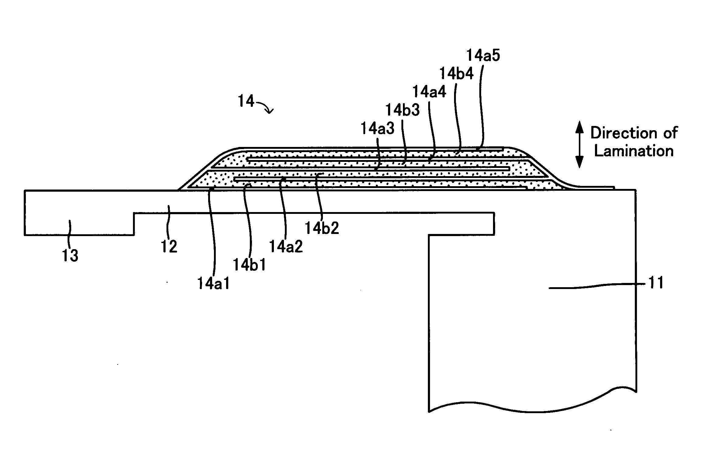
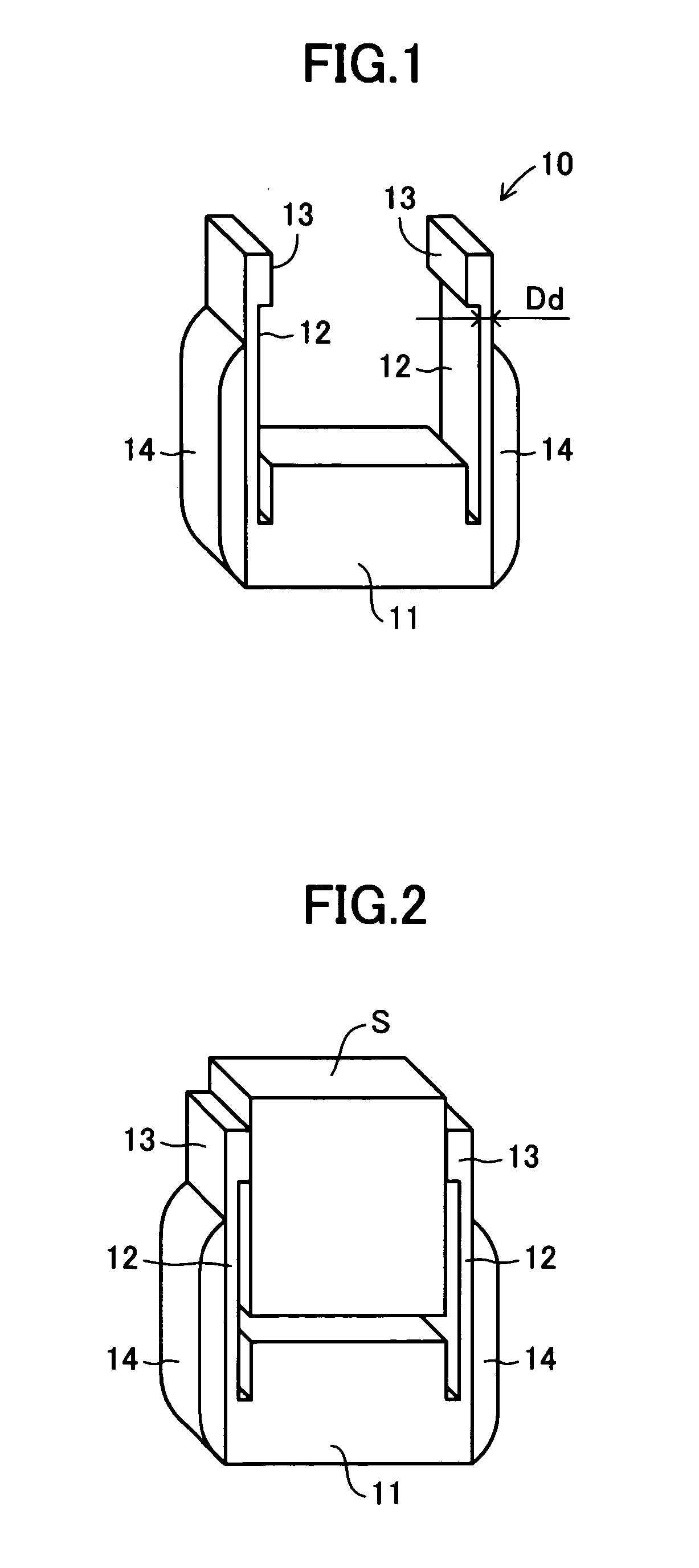
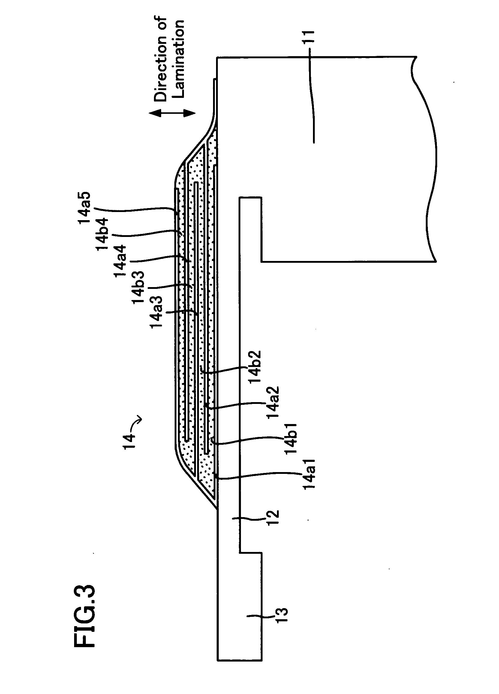
[0035] An embodiment of a piezoelectric / electrostrictive device according to the present invention will next be described with reference to the drawings. As shown in the perspective view of FIG. 1, a piezoelectric / electrostrictive device 10 according to the present embodiment includes a stationary portion 11 in the shape of a rectangular parallelepiped; a pair of mutually facing thin-plate portions 12, which are supported by the stationary portion 11 in a standing condition; holding portions (movable portions) 13 provided at corresponding tip ends of the thin-plate portions 12 and having a thickness greater than that of the thin-plate portions 12; and piezoelectric / electrostrictive elements 14 formed at least on corresponding outer surfaces of the thin-plate portions 12 and including laminar electrodes and piezoelectric / electrostrictive layers which are laminated alternately. The general configurations of these portions are disclosed in, for example, Japanese Patent Application Laid...


PUM


Abstract

A piezoelectric / electrostrictive device 10 includes a stationary portion 11; a thin-plate portion 12 supported by the stationary portion; and a piezoelectric / electrostrictive element 14 including a plurality of electrodes and a plurality of piezoelectric / electrostrictive layers which are laminated alternately. The piezoelectric / electrostrictive device 10 is manufactured as follows: firstly, a piezoelectric / electrostrictive laminate composed of laminar electrodes and piezoelectric / electrostrictive layers is formed on the surface of a thin-plate body which is to become the thin-plate portion 12; subsequently, the thin-plate body and the piezoelectric / electrostrictive laminate are cut; and the resultant cut surface (lateral end surface) is finished through polishing, so as to attain an arithmetic average surface roughness of 0.05 μm or less. This finishing process enables occurrence of uniform residual strain in the vicinity of the lateral end surface, as well as elimination of microcracks generated in the vicinity of the lateral end surface through the above cutting, thereby effectively preventing particle separation from the lateral end surface.

Description

TECHNICAL FIELD [0001] The present invention relates to a piezoelectric / electrostrictive device including a stationary portion, a thin-plate portion supported by the stationary portion, and a piezoelectric / electrostrictive element including laminar electrodes and a piezoelectric / electrostrictive layer. BACKGROUND ART [0002] Piezoelectric / electrostrictive devices of the above-described type have been actively developed as an actuator for precision machining; as an actuator for controlling the position of a read and / or write element (e.g., a magnetic head of a hard disk drive) for reading and / or writing optical information, magnetic information, or the like; as a sensor for converting mechanical vibration to an electrical signal; or as a similar device. [0003] Japanese Patent Application Laid-Open (kokai) No. 2001-320103 discloses an example of such a piezoelectric / electrostrictive device, which is shown in FIG. 13. The piezoelectric / electrostrictive device includes a stationary porti...

Claims


Application Information

Patent Timeline
IPC IPC(8): H01L41/04H01L41/083H01L41/09H01L41/187H01L41/22H01L41/337H02N2/00
CPCH01L41/43H01L41/083H01L41/094H01L41/273H10N30/2043H10N30/2042H10N30/50H10N30/053H10N30/097
Inventor IKEDA, KOJISHIBATA, KAZUYOSHI
Owner NGK INSULATORS LTD
Why Eureka
Try Eureka