
Exhaust gas-driven generator system and method of controlling electrical system

a generator system and exhaust gas technology, applied in the direction of electric generator control, electric generator control, dynamo-electric converter control, etc., can solve the problem of not satisfying the effect of utilizing exhaust energy, and achieve the effect of effective utilizing exhaust energy

Inactive Publication Date: 2006-06-01
DENSO CORP
View PDF50 Cites 60 Cited by
  • Summary
  • Abstract
  • Description
  • Claims
  • Application Information

AI Technical Summary

Benefits of technology

[0005] The present invention therefore has an object to provide an exhaust gas-driven generator system capable of performing power generation by effectively utilizing exhaust energy and to provide an electric system control method.
[0006] The present invention is based on a finding that, if a turbo generator is operated to generate even under a low engine output state, power generation will increase exhaust resistance causing a decrease in the engine output. To avoid this engine output decrease, it is necessary to increase fuel. It is thus desired to generate electric power by determining which one of power generation by an AC generator and power generation by an exhaust gas-driven generator is more economical.

Problems solved by technology

However, occurrence of such a high engine output as to cause exhaust flow to the waste gage valve is not so frequent that the effect of utilizing the exhaust energy is not exhibited to satisfaction.

Method used


Image

  • Exhaust gas-driven generator system and method of controlling electrical system
  • Exhaust gas-driven generator system and method of controlling electrical system
  • Exhaust gas-driven generator system and method of controlling electrical system

Examples


first embodiment

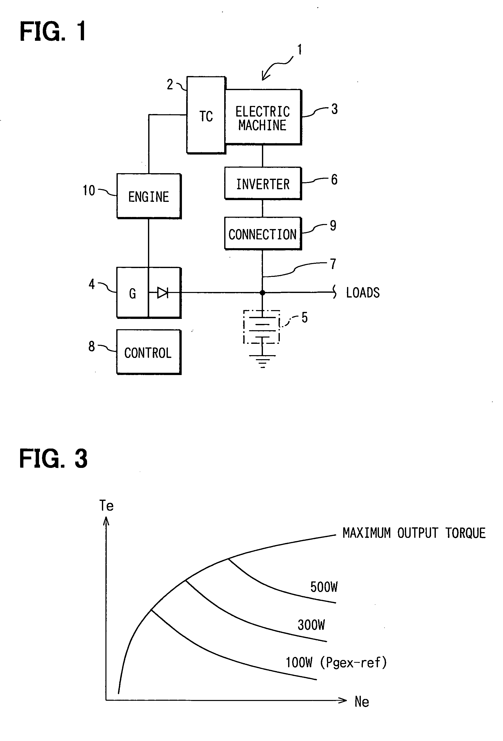
[0015] Referring first to FIG. 1, an exhaust gas-driven generator apparatus 1 includes an electrically-operated turbocharger 2 and a rotary electric machine 3 or an AC rotating electric machine directly connected to a rotation shaft of the turbocharger 2.

[0016] The turbocharger 2 may be driven by the rotary electric machine 3 to thereby perform compression of intake air of an engine 10. When the turbocharger 2 is not driven by the rotary electric machine 3, it rotates by absorbing exhaust gas energy of the engine 10. With rotational forces of the turbocharger 2, the rotary electric machine 3 performs electric power generation (exhaust gas-driven generation).

[0017] An inverter 6 converts DC power, supplied from a power bus 7, to AC power to thereby supply the electric power to the rotary electric machine 3. In addition, the inverter 6 rectifies the AC power generated by the rotary electric machine 3 and supplies the rectified power to the power bus 7.

[0018] An AC generator 4 is an...

second embodiment

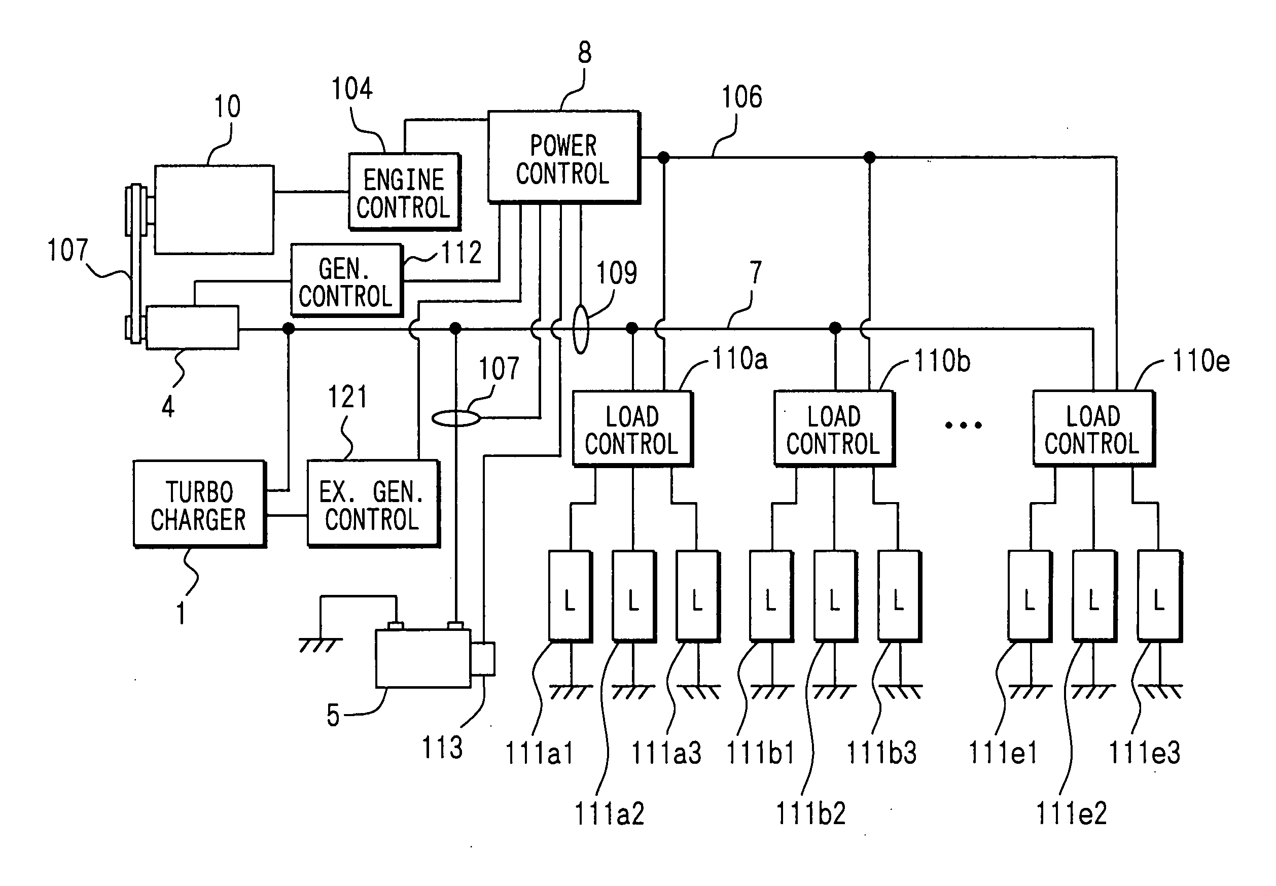
[0040] A vehicle power system utilizing the power supply system control method of the first embodiment is shown in FIG. 4 as a second embodiment. The vehicle power system of the present embodiment and the power control method are similar to those of a vehicle power system disclosed in US 2004 / 016461 6A1 the contents of which are hereby incorporated by reference.

[0041] In FIG. 4, an engine 10 is connected with an AC generator 4 through a belt 107. The generator 4 is connected to a storage battery 5 and load control devices 110a to 110e through a power bus 7.

[0042] Similarly, as in the first embodiment, an exhaust gas-driven generator apparatus 1 includes a turbocharger, which rotates by absorbing exhaust energy of the engine 10 and a rotary electric machine directly connected to a rotation shaft of the turbocharger. AC power generated by the rotary electric machine is rectified by an inverter (not shown), and the power is then supplied to the power bus 7.

[0043] The load control de...


PUM


Abstract

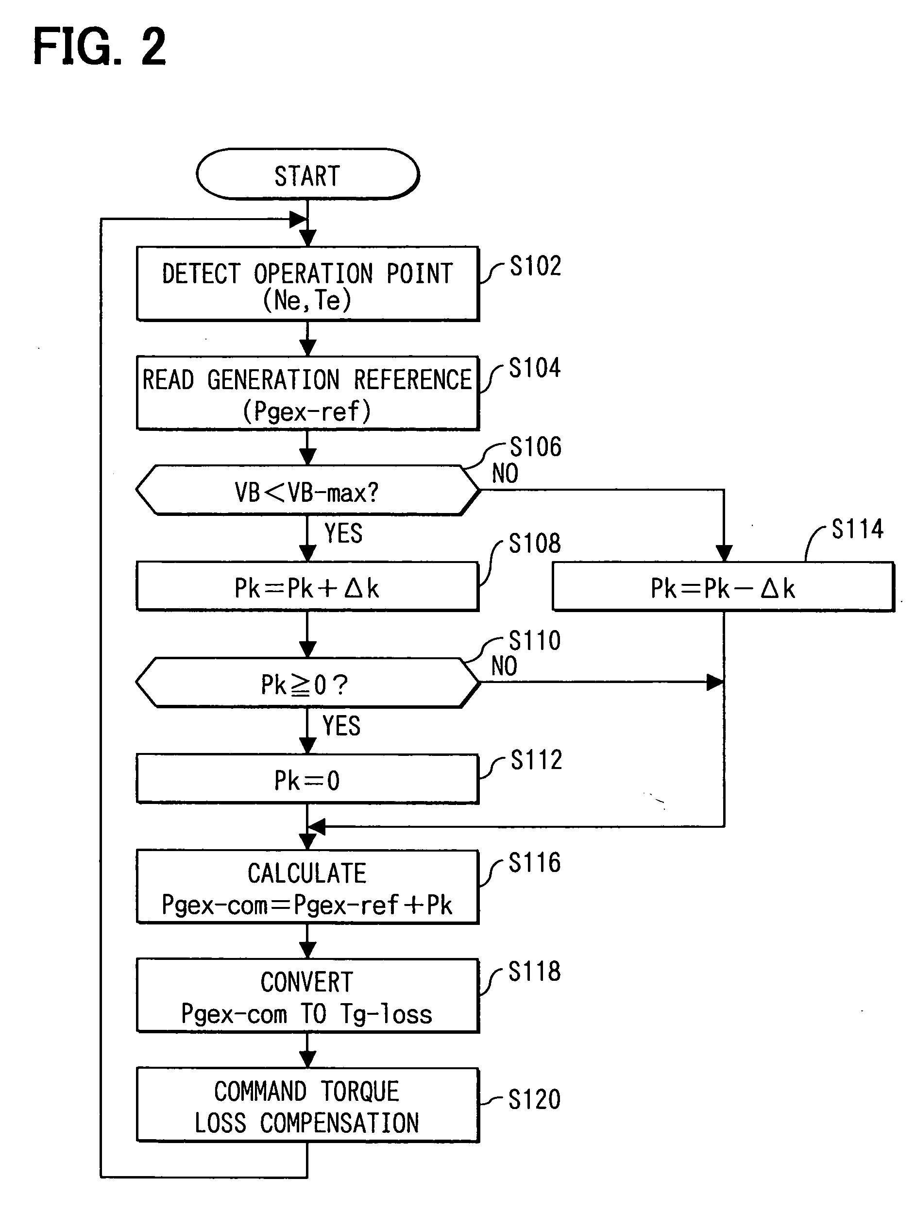
An amount of electric power generatable by an exhaust gas-driven rotating electric machine is determined corresponding to an operating point, so that an increment amount of fuel by the exhaust gas-driven electric power generation is smaller than engine-driven alternator power generation. The power generation can be thereby performed by effectively utilizing exhaust energy of the engine.

Description

CROSS REFERENCE TO RELATED APPLICATION [0001] This application is relates to and incorporates herein by reference Japanese Patent Application No. 2004-349044 filed on Dec. 1, 2004. FIELD OF THE INVENTION [0002] The present invention relates to an exhaust gas-driven generator system and a method of controlling an electric system of a vehicle. BACKGROUND OF THE INVENTION [0003] Various electric systems for vehicles are proposed for instance in US 2004 / 0164616A1 (JP 2004-260908A). [0004] Turbo generators for performing electric power generation by utilizing excess of exhaust energy used by a turbocharger are proposed in JP 2000-45817A. A turbo generator is configured to include a generator turbine disposed parallel with a turbocharger and an alternating current (AC) generator for performing power generation in direct connection with the generator turbine. The generator turbine is rotated by absorbing exhaust gas energy (exhaust energy) flowing through a waste gate valve that opens when...

Claims


Application Information

Patent Timeline
IPC IPC(8): H02P9/04F02D29/06
CPCF01N5/04F02B37/005F02D29/06F02D41/021H02J7/1423H02J7/1438H02J2007/143Y02T10/144Y02T10/16H02J7/143Y02T10/12
Inventor OBAYASHI, KAZUYOSHITANI, KEISUKETAMURA, HIROSHIFUJITSUNA, MASAMI
Owner DENSO CORP
Learn More