Scanner for probe microscopy

Active Publication Date: 2006-06-01
RGT UNIV OF CALIFORNIA
View PDF8 Cites 22 Cited by
  • Summary
  • Abstract
  • Description
  • Claims
  • Application Information

AI Technical Summary

Benefits of technology

[0016] The present invention overcomes the foregoing problems by providing a new type of scanner that avoids low resonance frequencies and accounts better for piezo nonlinearities. In accordance with one embodiment of the invention, we provide what we call a linear stack scanner. The linear stack scanner also uses piezo electric crystals as actuating components. However these piezos are not single crystals but are made out of insulated layers of piezoelectric material that are electrically connected in parallel. Arranging the single crystals in parallel increases the expansion range of the stack that is determined by the number of stacked single crystals. While each additional layer adds more capacitance to the stack to increase the capacitive load on the amplifier, and the mechanical resonance frequency of the piezo stack is lowered by each additional layer, coupled with the improved mechanical performance enabled by other embodiments of this invention, the linear stack scanner more than compensates for these effects.
[0017] In accordance with this invention, the x, y and z axes of the scanner are located perpendicular to each other and, are coupled to each other, but the piezos that actuate the axes are constrained in all directions except for the direction of the desired actuation. The sample area directly responds to piezo actuation with mechanical deformation within elastic limits, while maintaining x-y symmetry to enable image rotation. Speed performance is assured by rigidity in the actuation direction with high first order resonance frequencies, reducing mechanical oscillations while imaging. This is accomplished by each of several embodiments of the invention. In essence, this aspect of the invention provides a scanning probe microscope comprising a probe, a housing, and at least two actuators. Each actuator is coupled to the housing, and a support is coupled to the housing. The support is also coupled to at least one of the actuators at a position spaced from the point at which the actuator is coupled to the housing, for example, at an end opposite the end coupled to the housing. The support constrains the motion of the first actuator along a first axis while permitting translation along a second axis. The actuators are preferably piezoelectric but other types of actuators can be used, for example electostrictive, magnetostrictive, and / or electrostatic actuators, or even voice coils or electric motors. The actuators are preferably orthogonally arranged linearly stacked piezos, more preferably in push-pull configuration. The support can take different forms in different embodiments of the invention, as will be described below in detail.

Problems solved by technology

This has introduced problems relating to the sensitivity of the instrument.
However, it also results in a weak mechanical structure and therefore a low mechanical resonance frequency (˜800 Hz).
This is one of the primary speed limits of commercial tube scanners.
Another disadvantage of all kinds of piezos is their nonlinearity in operation.
Piezos are also unstable in their position over time, changing its expansion even with a constant actuation voltage.
These nonlinearities are a severe problem for the use of piezos as scanners for AFM as they distort the image, resulting in image drift and making it hard to find the same spot on the sample after zooming in.
This approach has several disadvantages: scanner parameters have to be measured for each individual scanner, with up to 30 parameters needed to model the piezo sufficiently; the behavior of the piezo is dependant on the DC offset, scan range and scan frequency; and position creep is unaccounted for by the modeling.
For the user of the AFM this results in: image warping (images are expanded in some directions and compressed in others); image drift; change of image center when zooming in or out; and incorrectly measured sizes of the objects.

Method used


Image

  • Scanner for probe microscopy
  • Scanner for probe microscopy
  • Scanner for probe microscopy

Examples


Embodiment Construction

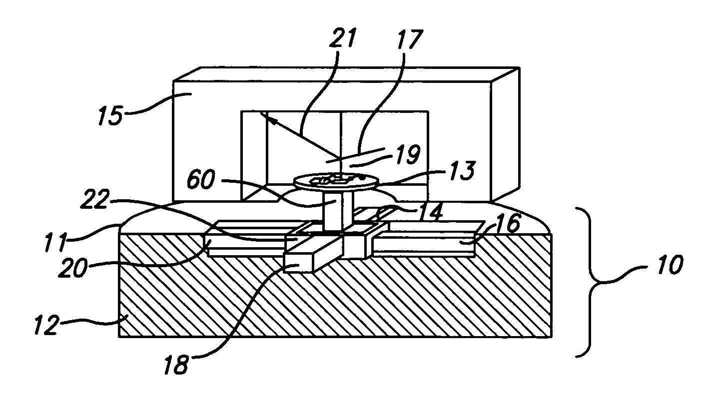
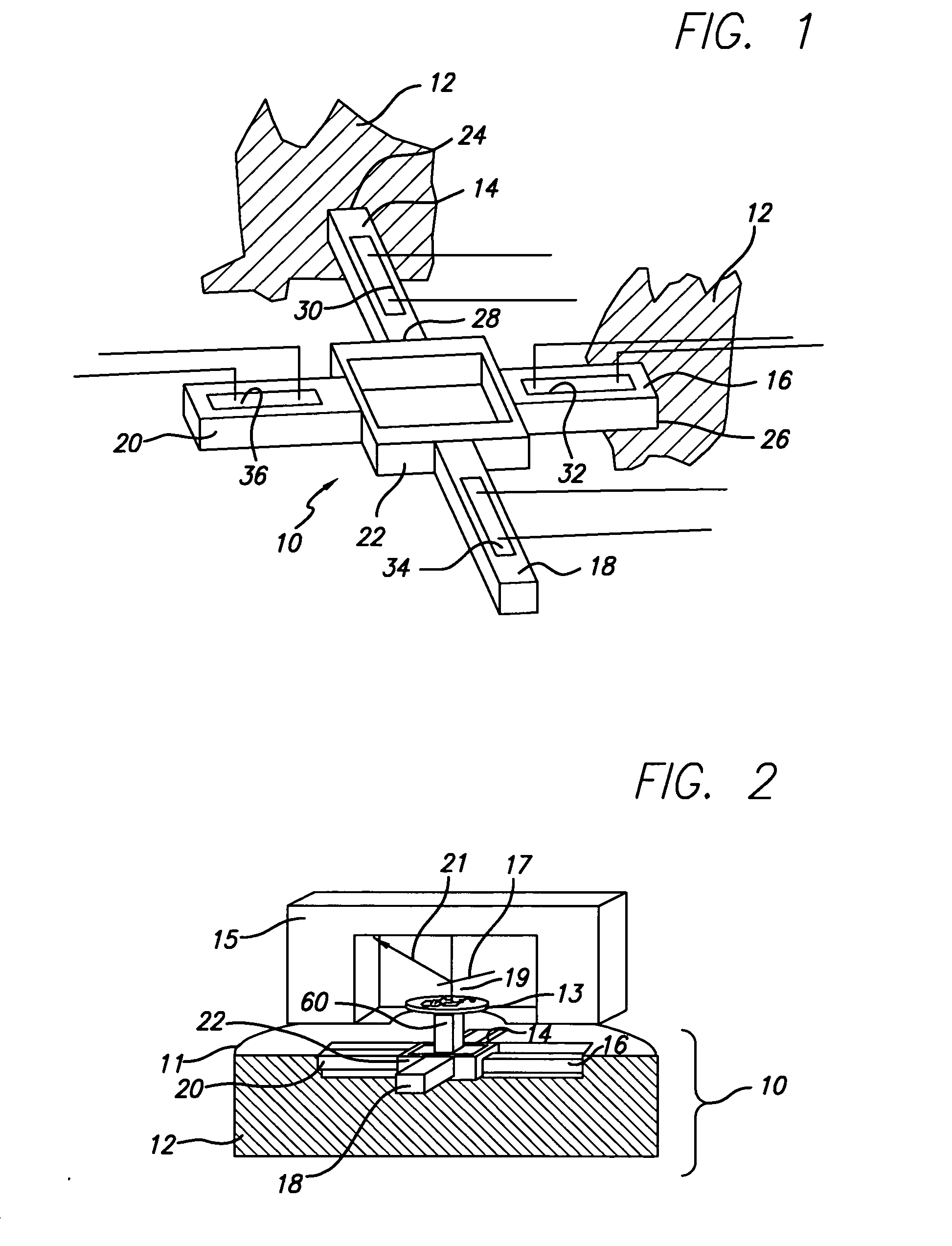
[0042]FIG. 1 schematically depicts generalized components of the scanner 10 for use in a scanning probe microscope of the invention. The scanner 10 includes a housing 12, at least two actuators 14 and 16 (possibly together with respective opposing actuators 18 and 20), each coupled to the housing 12, respectively at 24 and 26, and a support 22. The support 22 is also coupled to the housing (not shown in FIG. 1) and to at least one of the actuators at a position, e.g., at 28, spaced from the point 24 at which the actuator is coupled to the housing 12. The support 22 and its connections to actuators 14, 16, 18, and 20 are such that the support 22 constrains motion of each actuator along its axis while permitting translation normal to the axis. Strain gauge sensors 30, 32, 34, and 36 are applied to respective actuators 14, 16, 18, and 20 to enable measurement of expansion or contraction of the actuators.

[0043] Referring to FIG. 2, generalized components of a scanning probe microscope ...


PUM


Abstract

A scanner for probe microscopy that avoids low resonance frequencies and accounts better for piezo nonlinearities. The x, y and z axes of a linear stack scanner are partially decoupled from each other while maintaining all mechanical joints stiff in the direction of actuation. The scanning probe microscope comprises a probe, a housing, at least two actuators, each coupled to the housing, and a support coupled to the housing and to at least a first of the actuators at a position spaced from the point at which the actuator is coupled to the housing. The support constrains the motion of the first actuator along a first axis while permitting translation along a second axis. The actuators are preferably orthogonally arranged linear stacks of flat piezos, preferably in push-pull configuration. The support can take different forms in different embodiments of the invention. In a particular embodiment, the scanner is a 2D scanner having a support frame with x and y axes, and a member for supporting an object to be moved such as a sample for a probe, the scanner comprising a flexure and flexure coupled cross-conformed piezos arranged along x and y axes. Expansion of the piezos is measured by at least two strain gauges disposed to measure the differential motion of at least two opposed actuators. The strain gauges are preferably arranged to compensate for ambient temperature changes, and preferably two or more strain gauges of identical type are disposed on each actuator to magnify the strain signal.

Description

STATEMENT REGARDING FEDERALLY SPONSORED RESEARCH AND DEVELOPMENT [0001] This invention was made with Government support under Grant No. NSF-DMR9988640 AND NSF-DMR0080034 awarded by the National Science Foundation and by the National Institutes of Health under Award No. NCC-1-02037. The Government has certain rights in this invention.FIELD OF THE INVENTION [0002] This invention relates to the field of scanning probe devices. More particularly, the invention relates to improvements in an atomic force microscope used to measure the deflections of a cantilever. BACKGROUND OF THE INVENTION [0003] Scanning probe devices, such as the atomic force microscope (“AFM”) have proven to be excellent tools for imaging a wide range of materials such as metals, semiconductors, minerals, polymers, and biomaterials. In an AFM, forces are measured by means of a cantilever that deflects when forces act on it. The deflection of the cantilever is sensed by a detection system, commonly by focusing an incid...

Claims


Application Information

Patent Timeline
IPC IPC(8): G01B5/28G01Q70/04
CPCG01Q10/04B82Y35/00
Inventor HANSMA, PAUL K.FANTNER, GEORGKINDT, JOHANNES H.
Owner RGT UNIV OF CALIFORNIA
Why Eureka
Try Eureka