
Modular LNG process

a technology of lng process and module, applied in the direction of machines/engines, gaseous fuels, light and heating equipment, etc., can solve the problems of considerable capital expenditure to duplicate common facilities in each train, and achieve the effect of reducing the cost of these vessels, efficient and economical

Inactive Publication Date: 2006-06-01
BP CORP NORTH AMERICA INC
View PDF10 Cites 4 Cited by
  • Summary
  • Abstract
  • Description
  • Claims
  • Application Information

AI Technical Summary

Benefits of technology

The present invention provides a method for efficiently and economically designing a light hydrocarbon gas liquefaction process for the liquefaction of selected quantities of light hydrocarbon gas in an initial launch phase and one or more subsequent expansion phases to liquefy additional selected quantities of light hydrocarbon gas up to a maximum capacity. The method includes designing a launch train with facilities for pretreatment, refrigerant compression, cryogenic heat exchange, access services, liquefaction, and product storage and shipping. The launch train can be shared between subsequent expansion phases or designed for modular expansion as required. The method also includes processing the light hydrocarbon gas in the launch train to produce liquefied light hydrocarbon gas. The technical effects of the invention include reducing the expense of the liquefaction process by designing the launch train for shared use and modular expansion, and improving the efficiency and economics of the liquefaction process by optimizing the use of facilities and equipment.

Problems solved by technology

Clearly, the construction of separate trains of refrigeration processes as discussed above results in the expenditure of considerable capital to duplicate common facilities in each train, such as the dehydration vessels, acid gas removal vessels, and refrigerant compression and cryogenic liquefaction equipment.

Method used


Image

  • Modular LNG process
  • Modular LNG process
  • Modular LNG process

Examples


Embodiment Construction

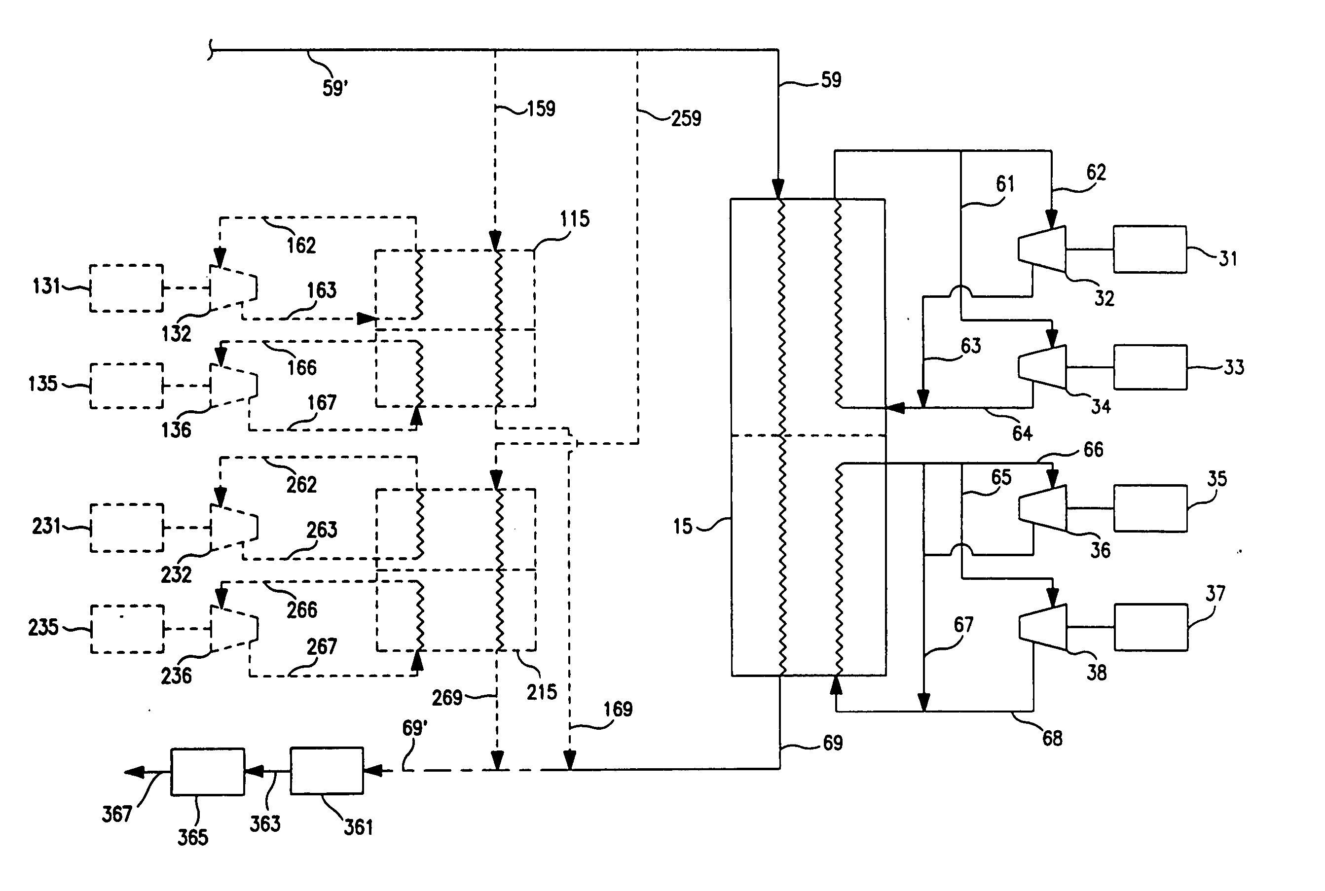
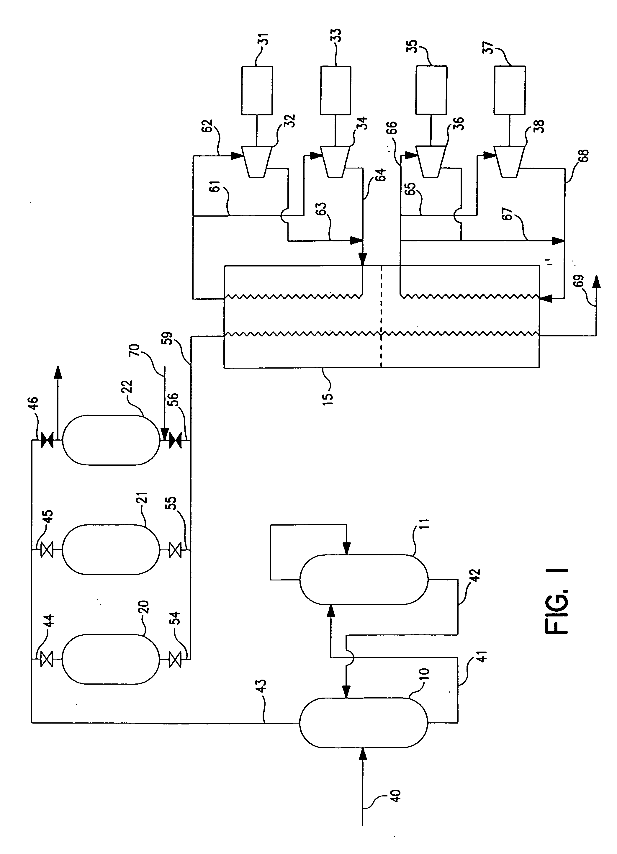
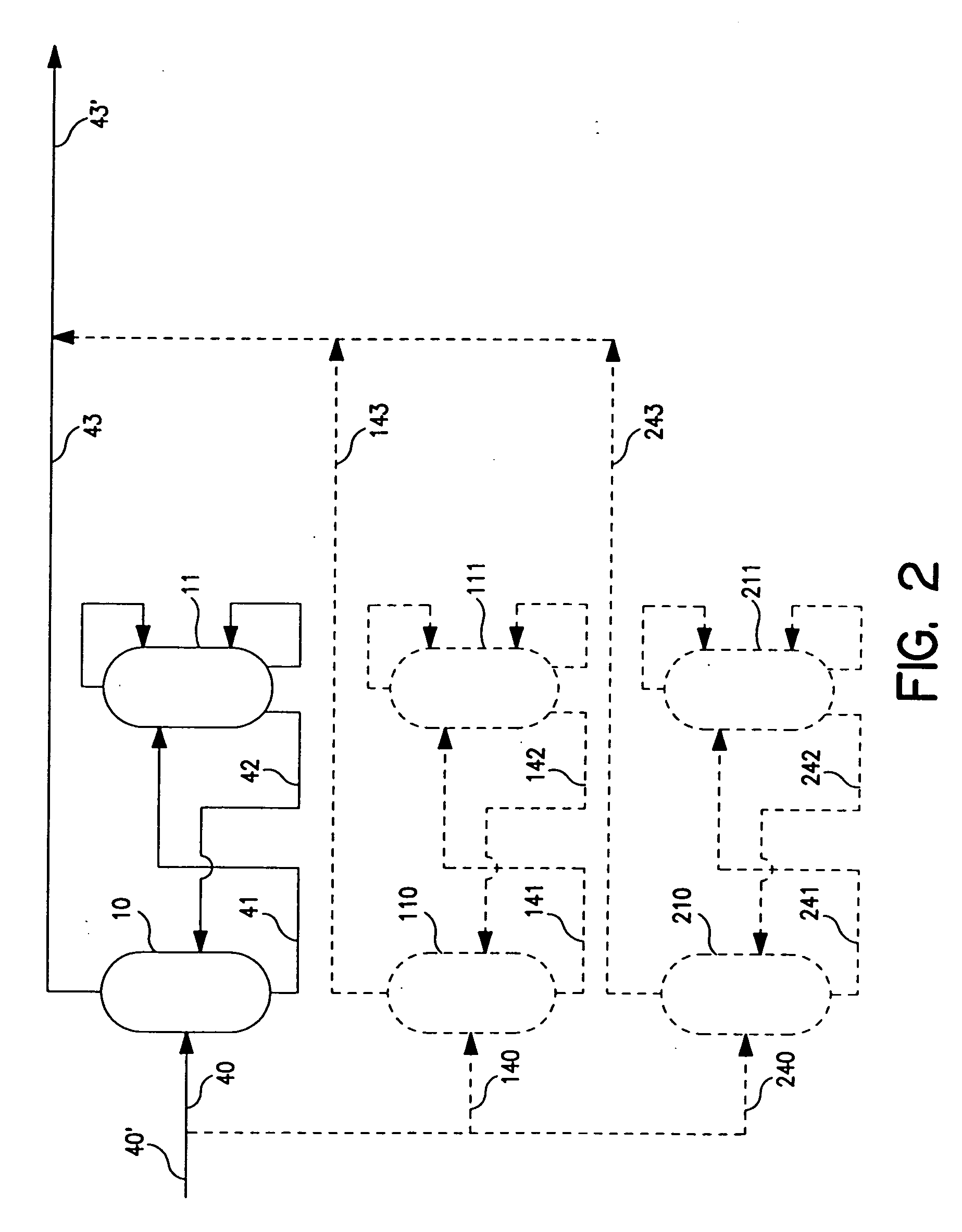
[0038] In the description of the Figures, numerous pumps, valves and the like, necessary to achieve the flows shown, as known to those skilled in the art, have not been shown for simplicity.

[0039] The present invention provides an improved efficiency and economy in operating a light hydrocarbon gas liquefaction process for the liquefaction of selected quantities of light hydrocarbon gas by use of an initial light hydrocarbon gas liquefaction launch train, and up to a selected maximum quantity of liquefied light hydrocarbon gas using one or more subsequent modular expansion phases by a method comprising the design of such process to include certain facilities which are common to both the initial launch train and subsequent expansion phases. As indicated the term “light hydrocarbon gas liquefaction train” or “train” refers to those units and facilities used for pretreatment and post-treatment of the gas feeds to the liquefaction facility as well as the facilities for compressing the ...


PUM

PropertyMeasurementUnit
boiling rangeaaaaaaaaaa
pressureaaaaaaaaaa
pressuresaaaaaaaaaa

Abstract

Disclosed are methods for efficiently and economically designing, constructing, or operating a light hydrocarbon gas liquefaction process for the liquefaction of selected quantities of light hydrocarbon gas. The method includes a light hydrocarbon gas liquefaction launch train to liquefy an initial amount of light hydrocarbon gas and one or more optional subsequent modular expansion phases to said light hydrocarbon gas liquefaction train to liquefy additional selected quantities of light hydrocarbon gas up to a selected maximum quantity of light hydrocarbon gas for the process. The methods employ shared use facilities, such as light hydrocarbon feed gas pretreatment facilities, refrigerant compression facilities, cryogenic heat exchange facilities, access services, other liquefaction equipment, and liquefied product storage and shipping facilities. The use of such shared use facilities allows for subsequent expansion phases or modules to be constructed to increase overall plant capacity, which can reduce the capital costs and space needed relative to prior methods for the design, construction, or operation of a light hydrocarbon liquefaction process which call for construction of a complete liquefaction train and all of its associated components and related equipment.

Description

RELATED APPLICATIONS [0001] This application is entitled to and hereby claims the benefit of provisional application Ser. No. 60 / 414,806 filed Sep. 30, 2002, the teachings of which are incorporated herein by reference in their entirety.FIELD OF THE INVENTION [0002] This invention relates to a method for liquefying variable selected quantities of light hydrocarbon gas to produce liquefied light hydrocarbon gas using plant facilities that comprise an initial light hydrocarbon gas liquefaction launch train with common shared facilities, which may be expanded by adding plant equipment associated with one or more optional expansion phases to the launch train. BACKGROUND OF THE INVENTION [0003] Many light hydrocarbon gas reserves are found in areas of the world that are remote to any markets for the light hydrocarbon gas. Such light hydrocarbon gas is referred to as natural gas. This natural gas may contain condensates that are light gasoline boiling range materials as well as C3-C5 gaseo...

Claims


Application Information

Patent Timeline
Patent Type & Authority Applications(United States)
IPC IPC(8): F25J1/00F25J3/00C10L3/10F01D15/00F01K23/06F01K23/10F02C6/10F02C6/18F25J1/02
CPCC10L3/10C10L3/102F01D15/005F01K23/064F01K23/10F02C6/10F02C6/18F25J1/0022F25J1/027F25J1/0283F25J1/0294F25J2205/60F25J2220/60F25J2220/64F25J2220/66F25J2220/68F05D2220/76F05D2220/72F05D2210/12Y10S62/902Y10S62/911F25J1/0214F25J1/0269F25J1/0274
Inventor SAWCHUK, JEFFREY H.JONES, RICHARD JR.WARD, PATRICK B.
Owner BP CORP NORTH AMERICA INC
Learn More